The Heybridge Railway, 1889 to 1913

Rob R

Western Thunderer
I have not added any extra weight to mine and she has managed a dozen or so wagons over a not too flat garden line.

There again, you have half of your boiler missing........
 

Richard Gawler

Western Thunderer
19. Underpinnings

Thank you to everyone for your continued encouragement.

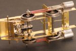
The class F is an important learning excercise for me for a few reasons, and especially because it is my first loco with suspension. At the moment, the front axle is in a frame and rocks sideways, and the rear axle is in bearings sitting loosely in the frames. This is as instructed for the kit, my only deviation has been to add some scraps of brass to stop the rear bearings rotating in the frames. One of these is visible in the photo.
DSC_4942.jpeg
I have now added some shim washers to remove the sideplay on the rear axle. Taking away about 0.6 mm of free play here is causing the motion to bind, just enough to make for a change in the sound of the motor.

The rear axle bearings are free to move most of 1.5 mm vertically and 0.5 mm front to back (there are no springs), and so I have my first floating gearbox and motor. And I am thinking, I could make my life easier if I soldered these axle bushes solid into the frames. Then the motor could be fixed to the chassis, and I would have a datum from which to tweak the rocking frame and the rest of the motion.

Please, does this sound sensible?

I think, there is so much slack around the rear bearings there is little benefit in having precision bearings here at all at the moment.
 
Last edited:

Rob R

Western Thunderer
Richard,
There shouldn't really be any play in the bearings "front to back". Excessive 'play' here, as opposed to a working 'clearance' of a couple of thou, means that your coupling rods and frames effectively have different hole centres, not a good thing.
I think you will need to tweak the little bits of angle iron either side of the rear bearings to take out the play but at the same time ensuring the axle centres still match the rods.
I would strip the wheels and cylinders off and reset it all using jig axles (see Simond's workbench thread).
Better done now than later with the brake gear etc in the way.

Edit: If you keep the rear bearings removable rather than soldering them in solid, then you still have the option of dropping the motor/gearbox out for future maintenance.
 
Last edited:

Richard Gawler

Western Thunderer
Thanks Rob. I agree, the coupling rods and frames really must have the same centres.

A while ago, I could lift the motor and gearbox combination out of the model. This stopped when I added the front to the firebox. Technically it was possible to undo the motor fixing screws, remove the motor and then the gearbox but I found this to be quite a fiddle especially during the reassembly. So I removed the brake rod below the worm so the motor and gearbox drop out underneath.

At the moment I can insert the rear axle when I install the motor and gearbox because I can remove the rear wheels from their axles.

DSC_4943.jpeg
I suspect, when I fit the rear brakes these will prevent me from taking the rear wheels off their axle or indeed putting them back on.

This is the first time I have looked at the brakes with very much thought. If they go nicely close to the wheels, any vertical movement in the axle bearings is likely to cause a short from wheel to brake to frame. I can accept this at the front because the axle is in a pivotted support and only one wheel at a time can cause a short. I cannot accept this at the back because both wheel bearings move up and down independently, and if both wheels touch their brake blocks I have a short circuit. Even if this loco has r/c with no pickups, such a short will interfere with control of any conventionally-powered loco on the track.

I am thinking, it might be best for me to solder the rear bearings solid and make the brake gear "removable with difficulty". For example leave the transverse brake rod loose in the frames with some washers added outside the frames to stop it moving sideways. Cutting through the rod would let me pull out the two brake shoes. Realistically, I shouldn't want to take the motor and gearbox out very often after everything is painted and set up.
 
Last edited:

Richard Gawler

Western Thunderer
I think I will get on best if I set the rear axle in fixed bearings. This will give me a datum to set up the front axle, I can secure the motor inside the firebox, I can set the brake blocks closer to the wheels and the model will always stand upright on the track. The brakes will have to be glued on after painting the chassis and adding the wheels but I can do this after I know the chassis is running well.

I will be able to swap the motor out but the gearbox will be trapped by the rear axle. I will have to remove the brakes to remove the axle to remove the gearbox and as long as realise this I should be fine.
 

adrian

Flying Squad
I cannot accept this at the back because both wheel bearings move up and down independently, and if both wheels touch their brake blocks I have a short circuit. Even if this loco has r/c with no pickups, such a short will interfere with control of any conventionally-powered loco on the track.
I would never take the risk and replace with either paxolin or plastic shoes - anything non-conductive!
 

simond

Western Thunderer
Richard,

I'm confused by your brakes. Is the fulcrum point really supposed to be below the pull rod connection?

(I would not fix the axle bearings unless I had to)


EDIT - just looked at Allen’s Sankey model, and see that this is how the brakes are, it’s a push rod.

cheers
Simon
 
Last edited:

Richard Gawler

Western Thunderer
Richard,

I'm confused by your brakes. Is the fulcrum point really supposed to be below the pull rod connection?

(I would not fix the axle bearings unless I had to)


EDIT - just looked at Allen’s Sankey model, and see that this is how the brakes are, it’s a push rod.

cheers
Simon
Yes, it is a push rod but the kit instructions call it a pull rod, which I couldn't understand. So I wrote, "operating rod".

But please, is there an overriding reason to not solder the rear axle bearings into the frames; or maybe is this a personal preference?

There is a lot of slack in the slots in the frames where the bearings sit, and I am going to find it extremely difficult to locate the bearings precisely opposite each other. I want to put the model in my Poppy's jig, add the extended axles and solder the bearings solid.
 

Rob R

Western Thunderer
There is no overriding reason, that axle won't be any different to the driving axle on the J15 and if it is all done on the jig it will be fine.
The main thing is that now is the time to do it before the brakes etc go on.
 

Richard Gawler

Western Thunderer
I have added a new frame spacer in front to the firebox. This makes a front for the firebox and improves the view between the frames, stiffens up this end of the chassis, and has let me add a vertical support for the motor.

View attachment 196232
It should be possible to tie the motor to this support or use a wedge to hold the motor upright against it. Solder tidied up after removing the motor and gearbox.

View attachment 196233
The motor support completes the structural work on this end of the chassis.

View attachment 196239
I ground down the motor spindle to let it clear the brake rod passing underneath. This could have gone better because the worm started to slide unseen towards the motor and so the shaft ended up 2 mm shorter than I expected. I have now secured the worm with 188-degree solder, this worked into the joint with Frys’ Powerflow flux and the micro flame torch. I can hardly recommend this approach but the motor does still run.

With the motor support in place I now have to separate the motor from the gearbox when I remove them from the model, but the motor fixing screws have good access from underneath.

This completes my modifications to let the model use the Mashima 1420 and the High Level 'Roadrunner' which it was never designed to accept.

When I added my vertical support for the motor, I was imagining tying the motor onto it with a cable tie. This seemed kinda neat but I had forgotten, the motor gets twisted relative to the gearbox during the worm meshing activity.

So, with the axle bearings soldered solid, and the final drive gear fixed onto the axle, the motor and gearbox will rock to and fro. The flat on the can of the motor may well not be quite parallel to my vertical support, but I can hold it onto the support with a dab of silicon or some other rubbery glue.
 

Richard Gawler

Western Thunderer
I cannot accept this at the back because both wheel bearings move up and down independently, and if both wheels touch their brake blocks I have a short circuit. Even if this loco has r/c with no pickups, such a short will interfere with control of any conventionally-powered loco on the track.

Richard, you could coat the shoes with a thin layer of epoxy or similar to insulate them

Ken

I would never take the risk and replace with either paxolin or plastic shoes - anything non-conductive!

DSC_4943.jpeg
I think there is enough metal here to open out the holes in the castings, wrap the wire supports in paper, and glue the brake hangers into place.

It is going to be really difficult to add the wheels after fitting the brakes, so the brakes can go on after painting and the subsequent rebuild and test running.
 

Richard Gawler

Western Thunderer
DSC_4949.jpeg
A final view of one of the rear wheel bearings before rebuilding them. When the model is upside down (like this) or standing on the track, the bearing sits in a half-round cutout in the frame. When I pick the model up, the bearing drops down onto its retaining wire. By design, the bearing can slide around in the frame. Its only stability comes from the axle, plus the strip of square brass and the shim washer I added.

DSC_4954.jpeg
I have plated over the holes in the frames and put in some plain 1/8 inch bushes. These bushes set up with care using a builder box for 00 gauge from Poppy's Woodtech. The bearings are in the spares box.

DSC_4956.jpeg
I have put a new brake pivot at the back, with a gap to let the motor/gearbox assembly go in and out of the model.

DSC_4965.jpeg
The alignment of the rear axle is spot-on. I have added different shim washers and ended up with an end float I can see as daylight but under 0.1 mm. The cable tie stops the motor tipping fore and aft, but I had to discard it because it stops the boiler fitting onto the model.

DSC_4957.jpeg
With the model carrying its 24 gram buffer beams it has enough adhesion to get 12 wagons underway. It was hinting at wheel spin with 14, but there is another 30+ grams of parts and batteries still to add.

In its state here, the loco weighs 220 grams and the wagons will be about 1.3 kg, which seems like a result to me. I suppose, having all four wheels on the track helps. More weight will reduce battery endurance so I maybe won't want to add extra ballast at all.
 

Richard Gawler

Western Thunderer
I forgot to mention, the model runs really well! When I powered it up with its new axle bushes there was obvious binding in the right hand side rod. I filed the cusps off the slots where the front bearings run, and the binding vanished.
 

Richard Gawler

Western Thunderer
I have not added any extra weight to mine and she has managed a dozen or so wagons over a not too flat garden line.

There again, you have half of your boiler missing........

I don't know how the performance of the Mashima 1420 compares with the Slater's motor/gearbox (now discontinued). The 1420 produces far less power than an 1833, so I guess 12 wagons says something about the efficiency of a railway. Running is almost silent so this will be a good reference when I come to try different underlays and ballast.

There is space in the firebox to put a motor 26 mm long but Mashima didn't make a 1426, only a 1626; and this would be too broad to fit.

Not wishing to antagonise those of a "very scale" disposition but maybe we can give them a race at a show with a twin loop test track :)
 
Last edited:

Richard Gawler

Western Thunderer
DSC_4970.jpeg
The pivot for the front axle assembly tends to sag and the model ended up about 0.7 mm nose down. The pivot also tended to act like a spring, which seems unnecessary with a rocking axle. I tried a length of piano wire here instead of the brass and this made everything worse, an undamped spring on one axle plus a rigid axle seems like a bad combination.

DSC_4968.jpeg
I have drilled and tapped the boiler and added a 6BA screw with a half nut to lock it into place. This lets me set the ride height.

DSC_4966.jpeg
The slot in the screw sits over the pivot wire, presses down on the front axle assembly and thus lifts the front of the loco.

I have added the length of wire across the centre of the chassis but I don't know what this is for. It is in the wrong place to line up with the reverser reach rod. Its ends fouled the sand pipes so I trimmed them back flush to the frames. I might end up cutting out the middle part too and leaving two scraps behind to hide the holes in the frames.

This build often seems like two steps back for each step forward, but I do think I have a workable chassis now. I can add bits to it (perhaps some copper clad pcb for pickups) but I shouldn't need to alter much.
 

AJC

Western Thunderer
I can see the issue with the pivot - what diameter is it? I wouldn't go below 1.0mm in 4mm - and generally nickel silver - to avoid the issue of deflection you clearly have here. You should be able to beef this up fairly easily (and I would do - that deflection and resultant nose-heaviness will only get worse).

Adam
 

Richard Gawler

Western Thunderer
The pivot wire is 0.7 mm diameter.

DSC_4350.jpeg
This photo is from a few weeks ago. There is very little metal available to drill out the axle frame to fit a stiffer pivot.

I did think about rebuilding the axle frame with some brass tube to take a much thicker pivot pin but to be honest, it is quite useful to be able to press the wire downwards to set the chassis nicely level on the track. So I think the slot in the head of the screw is quite an elegant workaround, because it is adjustable; and I thought of this myself too :cool:
 
Last edited:
Top