The Heybridge Railway, 1889 to 1913

Richard Gawler

Western Thunderer
The build is transitioning from the body to the chassis . . .
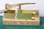
DSC_9722.jpg
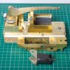
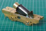
This is my first mock-up to see the overall look. I expect to trim the crane jib back to somewhere near the black mark above the rear boiler band. Only the tank sides and the front of the crane base are fixed but the fit of the parts is really good. Only the pliers are providing an external support. A well-designed kit in the hands of a beginner.

I could now finish most of the superstructure by following the kit instructions, but I need to have a think about Balance and the design of the chassis before then.
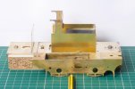
DSC_9736.jpg
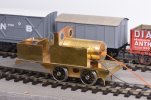
This is the build of the bodywork so far. I have put 67 g of lead into the tanks and the C of G of is now in line with the pencil.

My gut feeling is to add more lead here to try to put the weight of the body onto the four coupled wheels. The trailing axle could then be made up as a pony truck, essentially just going along for the ride and not supporting the model on the track.

The wheels have arrived and I think the sensible thing to do now is to build the chassis as an 0-4-0 and see it run on an umbilical cord. And then play up the design of the trailing axle and the arrangement of any more ballast weights.
 

Richard Gawler

Western Thunderer
Further to your query on the other thread, one good way of building an 0-4-2 is twin beams between the driving axles and a pivot on the rear axle.

Thank you Fraser for all of these ideas. 'Nellie' is my first attempt at a 7 mm loco; and my model has got to be limited by what is practical within the confines of the kit chassis; and what is sensible for me to tackle with a good chance of success. I want to decide on a configuration for my 0-4-2 chassis so I can try to build it.

The confines are:
  • the motor drives the middle axle (and the motor mount is to be soldered in to provide an additional frame spacer)
  • the chassis is designed to built rigid as an 0-4-0, with an option for the front axle to be rocking in elongated bushes
It seems to me,
  1. If my model has a fully rigid 0-4-2 chassis, it will behave as though it has three wheels and quite possibly only one of these will be a driving wheel – poor traction and likely to stall on uneven pointwork
    -> might be bearable with permanent DCC with a stay-alive fitted, but I want an analogue/DCC choice
  2. If the two driving axles are rigid but the rear axle can rock then the model will consistently behave as though it has three driving wheels and one carrying wheel, total four wheels – likely to run better than an 0-4-0 but may struggle on industrial curves
    -> needs pickups on all six wheels
  3. It the centre (driven) axle is rigid, and the leading axle is rocking, and the trailing axle is arranged like a pony truck with the ability to rock and turn, there should be all six wheels on the track all of the time . . . as long as I don't spring the pony truck so it lifts the centre axle off the track
    -> might work well with pickups on only the driving wheels
I am pondering, which of options 2. and 3. is a better one to choose? Perhaps 2, and if it doesn't work then try 3. I can borrow a Poppy's jig for setting up axle bushes. Of course, there may be a fourth and better/easier way.
 
Last edited:

simond

Western Thunderer
I think you have two options;

an 0-4-0 chassis, ideally with one rocking axle: the pony truck is only along for the ride - if your gearbox is fixed to the frames, this is probably the only realistic solution. This will require a chunk of weight in the smokebox.

a chassis with twin beam equalisation on the drivers, and a rocking carrying axle as Fraser suggests. My kit built 14xx is built like tis, and works well (the kit originally provided for rigid driving axles and a sprung carrying axle - this was a stupid design and gave utterly unacceptable performance). But this does require vertical movement on both driving axles. It will give better performance that the first option, and will not risk tipping backwards.
 

Richard Gawler

Western Thunderer
I think the motor mount has got to be rigid, so it will act as the frame spacer currently missing.

A sensible way to start would be to build the chassis as a rigid 0-4-0 and get the model to run with its extended footplate hanging out at the back with no crane. I can borrow a loco builder box (the Poppy's WoodTech one) from a mate, to help get the axles parallel in both planes. Add the crane, see what happens and if necessary add weights to compensate so the model still runs nicely. Only then add the third axle.

I imagine these locomotives must have travelled without their cranes so they could return to their works for overhauls. It would be good (but possibly too clever) if I could arrange the ballast weights so the C of G remains between the two driven axles regardless of whether the jib is present or removed. This will need some experimentation. I know the boiler and smokebox assemblies fit well (and weigh hardly anything) so I can put these to one side while I get the model running.

A club member has a Nellie with the side tanks "crammed with lead" and a rigid chassis. The model outhauls locos twice the size and this seems to be down to its all-up weight - most of a pound I suppose. Maybe, adding lots of lead between the tanks (each side of the motor) will be cheap and cheerful but effective.

I am in in a happier place than I was this time yesterday, I can see a plan of attack.
 

Overseer

Western Thunderer
As far as I know the crane on crane tanks were within the loading gauge so no need to remove the crane for travelling. This did mean that the cab roof would be lower or just a front weatherboard was provided so the crane could be mounted lower. Have a look for GER, NER or LNWR crane tanks to see how they did things. They were sometimes used to assist with derailments in the early days before larger dedicated cranes were available so needed their cranes when out on the main line.

Why not keep it simple and build the kit as intended with no compensation and add extension frames soldered to the inside of the kit frames (gives a little more space for sideways movement of the trailing wheels) with springing or weight on the trailing axle. If you add pick ups to the trailing axle it will improve the performance of the loco. You shouldn't need to add lots of weight, excess weight just results in bearings etc wearing out more quickly. You don't really need to worry about the centre of gravity, try it with no added weight then add some if you really need it. You could make a radial axle for the trailing axle for a little more challenge.
 

Richard Gawler

Western Thunderer
My source book for the crane part of the project is "Crane Locomotives" by R A S Abbott, published in 1973 by Goose and Son. This has plenty of pictures and some of the designs are really tall (and well out of gauge), especially the ones with the crane on top of the boiler. The design of my model is a medley of the prototype features I like and have the skills to build.

Anyway, the reason for adding lead to the model is to gain control of the C of G and to keep the front driving wheels on the rails. The notably heavy parts of the model are:
* motor
* jib (the weight is concentrated near the pivot)
* crew (two whitemetal figures)
* ballast weights inside tanks (doubled up since my last post mentioning them)

DSC_9750 (1).jpg

If cutting mat squares are our units, the crew are on the footplate and the name of a component represents its weight then I have to make sure,

( jib x 5.5 ) + (crew x 2 ) < (motor x 3 )

As it happens, the jib weighs much the same as the motor so clearly the jib will cause the model to rotate around its centre axle, lifting the front axle off the track unless I do something about it. I have put the ballast weights in the side tanks to do this, so now I only need

( jib x 5.5 ) + (crew x 2 ) < (motor x 3 ) + ( ballast x 3 )

Putting in the approximate weights in grams:

( 40 x 5.5 ) + (30 x 2 ) < (40 x 3 ) + ( 130 x 3 )
and indeed,
240 < 510

There's nothing like a few formulas to make a post difficult to read!

I don't know yet whether my crane jib is inside the usual loading gauge, but if not and I lift it off the model, the C of G remains between the driving axles and the model doesn't become nose-heavy. Hopefully, I don't need weight in the smokebox because this is in front of the leading axle.

The kit was designed for coarse scale wheels so the frames are rather narrow. I will put my additional frames outside the chassis and still have room for sideplay on the trailing axle, but thanks for the thought.
 
Last edited:

simond

Western Thunderer
I really do not recommend soldering that gearbox to the frames. You’ll likely distort both, and it’ll be much harder to make it run smoothly. The frame spacers are surely adequate as they are.
 

Richard Gawler

Western Thunderer
I am happy enough to leave the gearbox free to rotate; soldering it up is recommended in the kit instructions but I've ignored plenty of other parts of them.
 
Last edited:

Richard Gawler

Western Thunderer
DSC_9745.jpg
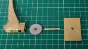
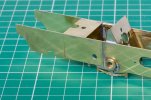
Yesterday I made the pivot for the crane jib and the base panel. The base panel will be fixed with four small magnets so I can lift it out to get at the decoder and socket underneath.

According to Gladiator Models' instructions for the crane, the geared rotating mechanism was used with the long jib version but not the short. The modeller's licence is coming into use here because I think the mechanism will make the model more interesting. Also, I've got the parts to make it.
 
Last edited:

Richard Gawler

Western Thunderer
As far as I know the crane on crane tanks were within the loading gauge so no need to remove the crane for travelling.
I have done some careful measuring of my model. I have set the jib so it just clears the roof of a half cab.
The top of the jib will be 71 mm above the buffer centre line, so a scale 122 inches
If the chassis leaves the buffer centre line a scale 40 in above the rail heads then the total height is 162 inches, so 13 ft 6 in.
I've made it by the skin of my teeth.
 

spikey faz

Western Thunderer
Hi Richard

I have the crane loco book as well and although I haven't referred to it recently I wasn't aware that some of the locos depicted were outside of the loading gauge. I suppose if they were purpose-built for a location then maybe not a problem.

I've built a handful of crane locos:

Crane Locomotives

and only the NSW loco would have problems with a loading gauge.

For what it's worth I found it far easier to balance out a compensated loco than a sprung loco. But that's just me! ;)

There's a new crane loco book coming out in July by John Woodhams. I shall probably buy a copy as I find these sort of oddball locos quite fascinating.

Mike
 

Richard Gawler

Western Thunderer
I've built a handful of crane locos:

Crane Locomotives

Mike, the vertical handwheel on your Wantage Tramway loco shows me, the locos with smaller jibs did have a mechanism to turn their crane jib; and the gears were hidden below the deck of the crane base. This clears up an unknown in the instructions from Gladiator Models. It also gives me the option to omit the large horizontal gear casting and lower the jib to suit as long as it still clears the cab roof.

I am rather enjoying making things up as I go along.
 

Richard Gawler

Western Thunderer
Me too! :thumbs:

Mike

Nellie and the 9F could not be more different, yet both are evolving in ways the kit designers probably never imagined!

This morning I decided Nellie would have a small coal bunker behind her left-hand side tank. This would be much like the arrangement on the Y7. I cut a hole in the top of the tank and a few minutes later saw the twin bunkers on your Wantage Tramway crane tank. The design of Nellie's coal bunker could have come out completely differently.

DSC_9756.jpg

DSC_9758.jpg
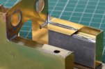
This little 'tray' can be filled with coal eventually.
 

Richard Gawler

Western Thunderer
Why not keep it simple and build the kit as intended with no compensation and add extension frames soldered to the inside of the kit frames (gives a little more space for sideways movement of the trailing wheels) with springing or weight on the trailing axle. If you add pick ups to the trailing axle it will improve the performance of the loco.
I will want to choose weight over springing for the trailing axle because I think this will be easier to set up. I built the K's kit (4 mm) for a 14xx and it was a pig to set up. It relied on a spring to hold the trailing axle on the track and either the trailing wheels fell off or the centre wheels lost traction.

You shouldn't need to add lots of weight, excess weight just results in bearings etc wearing out more quickly. You don't really need to worry about the centre of gravity, try it with no added weight then add some if you really need it. You could make a radial axle for the trailing axle for a little more challenge.
I have 130 g of lead sealed up inside the side tanks and the C of G will be in front of the centre axle, about a third of the distance towards the front axle. The C of G will move forwards but remain within the driven wheelbase if I remove the crane jib, so the loco should be always stable sitting on its four driving wheels.

The all-up weight of the loco will be about 500 g, I think this compares well with the Dapol 58xx at 700 g. My Minerva K class weights 470 g but spread over three axles. These three models represent from 155 to 350 g per axle, so really I have no idea of the optimum loading on an axle. I do think, I have roughly the right amount of lead and definitely in the right place to retain balance, so I think I can turn my attention to the chassis.
 

Richard Gawler

Western Thunderer
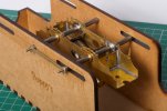
I borrowed a loco builder box by Poppy's Woodtech from a friend. The builder box uses extended axles (supplied with the box) and the loco coupling rods to locate the axle bushes in the frames ready for soldering.

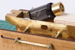
It took me less than an hour to set up the motor mount and the four axle bushes. I didn't take enough photos to show the whole sequence but they do show the highlights. This is my first 7 mm loco build . . .

DSC_9760.jpg
After the secondhand Mashima 1830 motor arrived I could see it wouldn't sit much lower in the frames than the 1833 one supplied with the kit. The extended spindle had been cut off the 1830, so I settled on the 1833. I will save the 1830 for a smaller prototype which can benefit from the shorter housing.

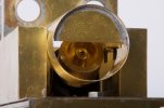
Investigations showed there is space for a flywheel inside the boiler so I bought the largest flywheel in stock at Roxey Mouldings, this is a Markits one 17 mm diameter, 12 mm long and a 2 mm bore to fit the motor spindle. The bit of plywood is holding the motor and its mount at the desired angle to get the flywheel in the right place.

The motor mount is about 1 mm narrower than the space between the frames. I had soldered in two scraps of fret to fill the gaps each side of the mount, and I soldered the motor mount onto these.

DSC_9772.jpg
Turning the chassis upside down I soldered the motor mount onto its associated axle bushes. (I had already soldered the bushes for the front axle so this was the third time the chassis went into the box).

DSC_9769.jpg
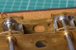
The chassis was designed for coarse scale wheels so the axle bushes have to be set outboard from the faces of the frames. I used a bit of 0.7 wire (top left) between flange and chassis to set up the location of each bush when I soldered it in. I have ended up with the outer faces of the bushes about 28.9 m apart. This is rather more than the dimension recommended in the instructions for the kit (28 to 28.5 mm) but maybe a lack of sloppiness will help the model to run in a straight line. Time will tell!

Afterwards, I tacked these bushes onto the outside of the frames to hold eveything solid. So the motor mount is fixed in four locations - the two bushes and along the tops of both frames.

DSC_9766.jpg
The flywheel tucks inside the fully-circular part of the boiler. Obviously this stops the body being lifted straight up off the chassis but there is going to be enough free space to manouevre the body on and off at an angle.

DSC_9786.jpg
So - I have the beginnings of my first 7mm chassis.

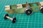
Afterwards I slipped the wheels onto their axles (omitting the worm gear) and trundled the chassis along the track by hand. There is no rock or any discernable twisting (yaw) motion and to be honest I am incredibly pleased with this. So far, I needed the broach only to fit the bushes into the frames; the axles are a perfect fit in the bushes as supplied.

I will report back here when the chassis has all six wheels on the track or I get stuck, whichever comes first.
 
Last edited:

Richard Gawler

Western Thunderer
Somehow, just as I expected, I have got all six wheels onto the track but I am stuck with the design of the rear truck . . .

DSC_9799.jpg
The loco has had its first run on the track under power, with the motor driving only the rear driving wheels. The model is stable over a reverse curve and through a Setrack point (approx. 40 inch radius). The worm and worm gear can mesh correctly.

DSC_9815.jpg
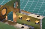
I have added my chassis extension pieces and their spacer, so the essence of the chassis is now complete. The hole beside the axle bush is deliberately off-alignment to help me move the plunger pickup away from the moulded centre of the wheel. The scribed line below the rear spacer is a mistake, this should have been on the inside.

This chassis extension went on crooked (perhaps 1/4 mm skew upwards), just enough to annoy. It came off with the blow torch to reveal complete coverage of tinning, which was good to see because I had soldered it on around the edges and the capillary had drawn the solder into the joint. Later, I made the same mistake with the second chassis extension but I noticed it after the first tack of solder.

DSC_9828.jpg
I have "made" the rear truck. This might end up as a radial truck or if this is too difficult a pony truck. I used some 3/16 inch square tube and two axle bushes soldered in to give me 29.3 mm B2B, i.e. the wheels rotate freely with no obvious lateral movement. I will leaving trimming the axle until later, in case I decide to use different wheels.

DSC_9826.jpg
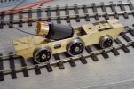
All together now. The loco won't cope with Setrack curves but it should manage a 4 ft radius as on this Marcway point.

And now I am stuck and I would like some advice please.

I am imagining, my rear truck needs a vertical pivot above the red pen X. This pivot could be a round bass rod telescoped inside a round tube fixed to an extra frame spacer. I can make this. The truck to be retained from dropping out by some wire links under the rectangular rebates in the chassis extensions. I can make these too. Some lead to be glued onto the truck to help it stay on the track.

Should I expect to arrange some springing as well, or maybe I can rely on the coning to make the truck centre itself?

I am making a working chassis not a scale chassis so I expect all kinds of mechanical arrangements are possible.

Many thanks.
 
Last edited:

Richard Gawler

Western Thunderer
Rob,

I think that's the way I would do it, over thinking these things can lead to later problems.

Hi Phil.

I am Richard, doing the build :thumbs:

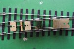
I have stood the chassis with its four driving wheels on a Setrack curve (c.40 inch radius). There is hardly any sideplay in the wheelsets, but I can move the rear end of the chassis about 5 mm sideways because of the slack between the wheels and the rails. This gets me thinking, if I can arrange the third axle to guide the chassis into the entry to a curve, and stay on the track running in both directions, then I will have done something useful.

I am a bit prone to over-thinking things. I need to accept, this is a model-making task not an engineering one. If it doesn't work as expected, I can dismantle it and try something different.
 

Richard Gawler

Western Thunderer
DSC_9837.jpg
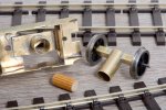
I have made a pivot for the non-powered axle from two pieces of concentric brass tube. I bought a pack of K&S offcuts a while ago, this is the first time I have made something useful from it.

DSC_9831.jpg
The inner of the two tubes makes a cavity where I can add some weight to hold the wheels onto the track. Experiments with a spring here failed miserably, though much as I expected. A spring from a biro latched onto the diagonal strap lifted the driven wheels off the track as a moment's notice. Gravity is better.

At the moment the cavity contains a piece of wooden dowel to limit the upward movement of the wheelset and thus stop the wheels climbing off the rails when they are leading into a curve. The rails are stopping the assembly simply dropping out completely.

DSC_9832.jpg
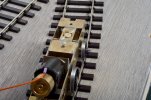
This shows how the wheelset is steering itself leading into a curve. I think this is more down to the wheel flanges than the coning. When the curve straightens out, the wheelset tends to over-compensate and steer the wrong way for while.

So - this arrangement seems to work, and with no springs in any plane. The wheelset seems happy with about 15 or 20 g ballast. I can provide this by extending a weight upwards from the pivot cavity into the crane base.

I was tempted to provide some kind of castor angle on the pivot i.e. make it slightly inclined from the vertical. This might encourage the wheelset to steer better when it is leading. But to my mind, the chassis has to work equally well travelling in both directions. Someone with a background in the car industry might be able to suggest whether I can expect to improve on this.
 
Top