A West Midlands Works

Scanlon

Western Thunderer
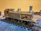
I use the weekends to work on my own loco builds and the E1 has progressed somewhat. On the frames the large transverse air reservoir has been fitted, just pipework to add once I have positively identified routes/positions from BR period photographs.

Considerably more work has progressed on the engine body. The handrails were first added this then gave me a position from which to install the vacuum ejector pipe on the drivers side. While on the firemans side, there is a lubricating pipe to the smokebox. A start was then made on cleaning up the white metal castings. The locomotive I am building had the whistle mounted on the safety valve cover unlike most others which had it mounted on the cab roof.

While some modellers will disagree, I consider the E1 to be a Terrier on steroids! Reviewing both SR and BR period photos, and in the absence of anything to the contrary, I have used the A1X rebuild as my guide for the position of the bottle valves for the steam feeds to the injectors. As on the Terrier, BR photos show these valves to be immediately behind the dome. Also, as my E1 is a modern image build (a term coined by a fellow LB&SCR fan) the dome has been located further forward. I used an E1R diagram to assist getting the positioning correct after reference to part 2 of Bradley’s Locomotives of the LB&SCR.
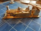
20220926_153911.jpg
Quite a lot more detailing is yet to be added, not least the smokebox door. The largest area requiring attention is the cab interior. So, with the smokebox door just put in position and the frames and cab roof added the build has reached this stage.
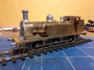
20220926_161043.jpg
20220926_161112.jpg
Lots of cleaning up to do as you can see.
 

Scanlon

Western Thunderer
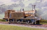
The little E1 is now with Paul Moore for painting.
20221122_090007 (2).jpg
My Standard Tank has now returned from Ian Rathbone and has a wonderful coat of paint and light weathering, here the loco is working an inter-regional train on Bucks Hill.
80011 101222 (2).jpg
My latest commission build is a DJH Clan. Work commenced in September but assisting with arrangements for the Warley National Model Railway Exhibition have taken up most of my time. Only recently have I been able to restart this build. This is my first DJH build and frankly I am not impressed.

Work commenced on the tender and I was pleasantly surprised to see many of the etches were pre-formed. This turned out to be fools gold as the lower radii for the tender sides were incorrectly rolled. The basic tank etch consists of both sides plus the rear but I do not have rollers which could accommodate an etch of this length. A lot of heat plus the use of numerous bars eventually produced the desired effect. This is the final result of all the work on the tender, the large rectangle hole to the right will be filled by a water gauge.
Tender 3 201122.jpg
During lulls in my Warley workload a start was made on the engine frames. As usual they were built up on the chassis jig.
Engine frames 1 111022.jpg
It had been hoped to motorise the model using the rear axle but found myself frustrated by a big etch to support the lower part of the boiler and the rear of the frames above the pony truck. To make matters worse and in discussion with my customer, if the motor etc. was fitted on this axle there would be no simple way to fill the huge void in the boiler which would otherwise arise. This photo shows the raw castings forming the boiler.
Boiler casting 2 101022.jpg
The recommended Slaters motor and gearbox fills this void but it will be very visible when the whole loco is assembled. The Clan boiler being somewhat smaller than that on the Britannia.

The bogie and pony truck were built up and a start has been made on detailing the frames and cylinders. The brake gear is a mix of white metal and etches. To ensure there is sufficient clearance for DCC operation the rear of the brake blocks have been chamfered. The cylinders and reversing supports are fitted using metric bolts in pre drilled holes. No nuts are provided in the event the holes are too big and of course they proved to be. Fortunately, I have a supply of metric nuts of the right size. However, I do not understand this form of assembly because the slidebar supports are solder into the frames with the slidebars permanently fitted to this support and the cylinders. With the slidebars and crossheads fitted the side and connecting rods have been built up and everything tested.
Engine frames 7 091222.jpg
The leading coupled wheels are currently lifted off the track because the bogie has a very stiff spring on the centre spigot. When the massive boiler casting is in place, I feel sure the wheels will sit properly on the rails!

I am about to start building the cab and the very complicated build diagram is only accompanied by about nine lines of instructions. How a first-time builder can cope with this degree of secrecy within the build instructions is beyond me.
Cab inst. 2 131222.jpg
and
Cab inst. 1 131222.jpg
Time will tell.
 

Attachments

  • Loco 4 121122.jpg
    Loco 4 121122.jpg
    248.6 KB · Views: 9

Scanlon

Western Thunderer
Hi Dave,
It will be interesting to compare notes. Whenever I get a kit to build from a supplier I do not know e.g. DJH I tend to follow the build instructions almost to the letter. The build instructions for this loco are in my opinion very poor. This is a complicated loco and following all the little lines around the various pages does my head in!!!!! To make matters worse some of the parts are not identified so what a newby is to do is anyone's guess. Thankfully BR Standards are my "bread and butter" but this one is a trial.
 

mickoo

Western Thunderer
Hi Dave,
It will be interesting to compare notes. Whenever I get a kit to build from a supplier I do not know e.g. DJH I tend to follow the build instructions almost to the letter. The build instructions for this loco are in my opinion very poor. This is a complicated loco and following all the little lines around the various pages does my head in!!!!! To make matters worse some of the parts are not identified so what a newby is to do is anyone's guess. Thankfully BR Standards are my "bread and butter" but this one is a trial.
Well, having written a few instructions I can say they're not easy to accomplish, in addition, listening to a lot of feedback at shows' it's quite interesting to see how different peoples minds work.

For myself, the exploded cab view works perfectly and I can see everything I need to see, I would have no issue building that cab from that picture alone....but...I am pictograph orientated and we form about 25-30% of the population and mostly people with engineering type talents. Shapes, orientation and construction I see very easily.

The rest are generally written orientated, they struggle with pictographs but read the written word very easily, I can't, I become word blind and frustrated, I got tired of reading after (E151) on the first line and I say that sincerely, not for affect.

Good instructions have a healthy mix of both, preferably all pictograph and all written, each a mirror copy of the other but in it's own format, generally speaking that doesn't happen and you'll get a variable cross over spread between the two.

Interestingly, the QA step after my initial formation is by a person who is strongly biased toward the written aspect.

For me, I don't think that page of instructions is poor, that exploded diagram is actually quite (almost very) good, it's clean, neat, orientated and scaled well....not like some higgly piggly hand drawn scrawls you see. However, for someone not pictograph orientated then I can see how they would struggle. I will concede that as a set of instructions that is supposed to meet both types then they are found to be wanting.
 

simond

Western Thunderer
I agree with Mick in this, however, though an Engineer by profession, I do like the words to go with the diagrams.

in this case, I’m not sure what more words would do to help. Perhaps if the steps were printed as a numbered list, but the steps do appear to be there, and presuming the part numbers are visible on the frets, it seems clear to me.

I suspect a couple of other images from other orientations might be helpful, and critically, an image showing the first folds for folks to whom this loco family is not so familiar. Getting the four (?) front cab folds right gets you a long way, and gives confidence for the soldering.
 

Richard Gawler

Western Thunderer
The exploded diagram seems clear, perhaps two or three diagrams each showing fewer parts would be better, but not at all bad.

I like having some narrative to support the diagram (and not the other way round), but what what we have here could be expressed better. In particular, use words more consistently and in only one part of speech (we have screws as a noun and screw as a verb) and use a controlled vocabulary so words like fit, install and attach can each refer to specific methods of assembly such as adjust size to fit, attach with bolts/screws, and fix using solder.

The last sentence ("fit the roof and remainder of the detailing parts") looks like the writer felt obliged to write something but has said so little they leave the reader wondering what on earth the detailing parts might be and whether the roof goes on first or last, not so good.
 
Last edited:

Scanlon

Western Thunderer
It's been a while since I last posted on this thread. Life had become somewhat hectic and I completely overlooked keeping this thread updated. Paul Moore has finished the painting of my little E1 tank which I'll collect at Stafford.
IMG_1586.jpeg
The Clan is completed and goes to Paul for painting very shortly.
Loco 15 270823 (2).JPG
Similarly a Stanier Mogul has crossed my workbench. It is almost complete having reached this stage.
Loco 8 190823 (2).jpg
Valve gear parts from Premier Components are being collected at Guildex and I expect this loco will be ready for painting in a couple of weeks. For a superb description of the build of one of these kits I refer you to PAD's thread of his build.

I am now working on a loco for my collection, more to follow.
 

Scanlon

Western Thunderer
Along with a lot of other modellers I have been waiting for the badly delayed MOK 75XXX kit. No one foresaw the health emergency which pushed all projects into the unknown however, Dave Sharp continued working away and has produced a magnificent kit. I collected mine at the 2022 Guildex and work started on it in February. My loco will be 75075 with a double chimney and a BR1B tender.

Work commenced on the tender in February. This was a relatively straightforward; this photo shows the basic inner framework.
Tender 080223 (1).jpg
Adding the outer “skin” to the tender followed standard MOK practice and fitted perfectly into the castings for the lower curve. Detailing followed the instructions and only doors have yet to be added.
Tender 7 290823.jpg
Cleaning up will start soon.

With the tender built work commenced on the engine frames. The build instruction book is very comprehensive and given the complexity of this kit I follow them almost to the page. The first step was to prepare all the frame stretchers and solder on dozens of 12BA nuts some of which can be seen here.
Frames 1 250223.jpg
Everything fitted exactly as expected and the entire frame was initially constructed with a minimum of solder. All the internal framing plus the ashpan must be put into the inner frames as it is impossible to add anything which might have been missed out at a later date. The basic frames were put onto the chassis jig to ensure they were square while everything was soldered up. With this completed all the tags had to be ground off before overlays hid the “Passchendaele” look. The lower part of the firebox is formed of two large casting which are bolted into the frames.
Frames 5 010323.jpg
Cylinders, sandboxes etc. have since been added.
Frames 8 250423.jpg
An error on my part was to fit the brackets for the sand pipes too early into the build. They are very vulnerable castings and I have created unnecessary work for myself. Unfortunately, a casting for the left-hand motion bracket had not been cast properly and this has delayed work on the frames for a while.

Work on the engine body has had to take a back seat due to getting two commissions completed but various modules could be built as time allowed. The firebox is made up of five large casting which have to be built up on an inner frame. A little fettling was required to dress joins etc. but this element of the build was straightforward. The boilerbands are located by tiny 0.5 pegs which slotted exactly into place first time.
Firebox 1 090523.jpg
The bracket for the injectors was then constructed and is a little gem. All the major pipework is provided in various castings, approximately 30 in all. The few used so far have fitted first time! This photo hardly does justice to the castings.
Injectors 1 290823.jpg
On the other side of the loco is the AWS battery box and other equipment; in error called ATC in the instructions. Again, a little masterpiece is the result.
Cab 3 110523.jpg
As you can see the basic cab frame hasd also been built.

Fortunately, my commissions are now complete or almost finished so the build has reached this stage.
Loco 2 290823.jpg
A very satisfying project so far.
 

P A D

Western Thunderer
Excellent work Roger.

I want one! Or maybe the BR or Ivatt mogul. It's a while since I finished the 4MT and I'm getting MOK withdrawal!

Cheers
Peter
 

chigley

Western Thunderer
I spoke to Dave last night and he's redoing the rebuilt w/c but he wants opinions on white metal or resin boiler
 

Richard Gawler

Western Thunderer
Roger thank you especially for the photos of the chassis. This is the first time I have had a clue of what goes into these in a modern kit.
 

Scanlon

Western Thunderer
While work slowly continues on 75075 I am once again indulging my passion for locos from my favourite railway LB&SCR, albeit in the BR period. A chance look at Steamlines drew my attention to an alleged LNWR 0-4-4t which as Chris Aldred noted bore a huge likeness to an LBSCR D3 tank. I had to have it, subject of course to inspection and Chris agreed to bring it to Stafford. Frankly it is/was a basket case but I can be a sucker for basket cases! The loco is from the former MSC range and I have been looking for a kit or built model for at least 12 years. I know ACE Products have this kit in their catalogue but it is only available as a special etch. This is what Chris presented to me.
Original 3 040923.jpg
Original 2 040923.jpg
After a little negotiation I bought the loco. It has a Premier Components frame, Slaters wheels and a simple fold-up gearbox with a Canon 1833 motor. Overall, it was not in too bad shape but goodness knows what the original builder followed regarding pipe runs etc. Shortly after getting back from Guildex the body was given a bath in cellulose thinners so I could see exactly what my new acquisition was “made of”. This was the result.
Loco 1 040923.jpg
The bath revealed a basically well-built loco with not too much solder on show although where it could be seen there was masses of it. Using a set square the build was checked. Only the left-hand tank was showing a slight problem where the running plate was not level and throwing the tank out of square. Most of the castings were fine although the chimney had a somewhat rakish angle reminiscent of the Titanic. The area of greatest concern was and is around the smokebox saddle where the original builder has used left hand etches on the right and vice versa!

During the week I have trawled through my spares boxes and found most of the replacement fittings I need. The loco I intend to build will probably be 32390 the last one in service although two others could be candidates. These locos when in service were latterly overhauled at Ashford works and acquired flat smokebox doors and many of them were fitted with Ramsbottom safety valves. In my opinion these modifications spoilt the loco but fortunately all 3 locos I favour retained the LBSCR safety valves. However, a flat smokebox door will definitely not appear!

Yesterday I started to dismantle the model and preliminary rectification to the left-hand tank and running plate undertaken. Using clamps, I heated the bottom of the tank and it sprung back into position and correctly “hugs” the boiler, the running plate is also greatly improved. A major requirement was to remove the cab roof which revealed a cab layout that could never have worked in reality. Needless to say, this will be rectified.

The frames require very little work. The major alteration will be to the brake gear which is completely incorrectly assembled. Also, the etches are representations of the wooden brake blocks used when first built. Naturally these will be replaced.

The rebuild has now reached this stage with lots to do.
Strip 2 090923.jpg
 

P A D

Western Thunderer
Hi Roger,
You're a brave man (for someone who can't build;)).

I saw this on the Steamline stand and thought it must have been built blind folded.

However, I'm sure you will raise it from the dead.

It was nice talking to you at Guildex. I'm sure we've met before but I can remember where.

Cheers,
Peter
 

Scanlon

Western Thunderer
Hi Peter, Good to meet you at Guildex and I'll do my best to raise this loco from the dead, a start has been made on rebuilding.

As this photo shows these locomotives had pull rods for the brake gear located outside of the driving wheels.
32386 Lewes 0451 (2).jpg
Copyright Smugmug.

Those on the model were assembled incorrectly but as I don’t have the original build instructions I cannot say if this is builder error or intentional by the kit manufacturer. However, it turns out all the brake gear was built up entirely from whitemetal castings and it had to go. This is what I started with.
Brakes 1 100923.jpg
A rummage through my spares produced brake hangers and blocks which with a little fettling look somewhat like the later equipment fitted to these locos. Brake stretchers were found and 0.8mm wire extensions were soldered into place for the lower fixing points. With the original fittings removed I marked out the frames to drill holes for the new hangers. The replacement hangers and stretchers were installed and delicately soldered in position. The pull rods were made from 1.4mm scrap etch and a representation of the mechanism for the hand brake built up from spare etches after referring to prototype photos.. This is the end result.
Brakes 3 100923 (2).jpg
A lot of cleaning up has to take place and the final angle for the hand brake rod will be adjusted when the body is in place. As currently installed the bogie moves side to side without any interference.
 

Scanlon

Western Thunderer
Back to the 75XXX and today was detail the smokebox door.
Smokebox door 2 110923.jpg
The photo has shown some stray solder which has since been cleaned up. The two irons on the lower door are necessary for locos of the SR and will be slightly shortened to reflect the prototype.

Tomorrow a start will be made on detailing the cab. There is a myriad of tiny etches to fit followed by an equal number of fiddly castings to tidy up and then put onto or in the etches. Wish me luck.
 

Scanlon

Western Thunderer
These photos show today's progress on detailing the cab. Not a lot to show for about 5 hours work but at least there is progress.
Cab 5 120923 (2).jpg
This is the Drivers side, the controls for the ejector were very difficult to fit, early on in the instructions the builder is told to extend a wide slot downwards, but this should have been horizontal. Consequently it was very difficult to obtain a tight fit between cab front and the casting.
Cab 4 120923 (2).jpg
The fireman's side and the camera is cruel, I've forgotten to fit a pipe to the pep pipe and its operating wheel. Oh well more for tomorrow.
 
Top