7mm David Andrews Princess - 6206 Princess Marie Louise

Rob Pulham

Western Thunderer
Even so, milling round wire to make it half round, whatever happened to just filling a flat on it :confused:
If I had just needed the one short length, I would have done just that, but I needed a few and I have a large stock of 1.5mm brass rod and a milling machine. That and the last time I wanted some 1.2mm half round I couldn't find any. Metal Clays 4U you were out of stock and everyone else only had sub 1mm
 

Rob Pulham

Western Thunderer
till working on the body details, I next approached the Injector pipe that runs along under the footplate on the right hand firebox side.
This is the casting supplied.
53484984080_40cb2e8d59_4k.jpg

For Christmas, I received a new four jaw chuck for the lathe and wanted to give it a try so I decided to make the jointing flanges first. I had a length of brass bar which was the right outer size without further machining so I centred it and drilled it 3mm. Just to be sure I also ran a 3mm end mill through it. Finally parting it off to length

53480550009_5da8860c82_b.jpg

I turned a 3mm spigot on the end of a piece of rod from the useful bits box and fitting the workpiece to it I mounted it in the dividing head and used the stub of a cheap carbide drill that I had reground after it broke off to spot drill each corner. These cheap Japanese carbide drills are very good but incredibly brittle even the act of bringing them down to the workpiece can break them off, if you are slightly heavy handed.

53486298833_0885912969_h.jpg

Then I drilled them 0.7mm and fitted wire and tube hex nuts to complete the part.

53480238371_33246f619a_h.jpg

53480238441_cd446b9f86_k.jpg

Next I turned a small top hat flange for the other end and then bent the pipe to shape before finally adding retaining straps from scrap etch strips and more 0.7mm wire.

53484578546_4580c1a64a_4k.jpg

53486126376_8da9f7f141_4k.jpg

Onto the next...
 

Rob Pulham

Western Thunderer
There were no other pipe castings included in the kit. But there was a casting for a pipe flange for the smaller diameter pipe but only the one.

In the end up I wasn't happy with the first pair of smaller pipe flanges because I hadn't managed to get the centre hole in the middle. The cross section of the bar that I used was too small for the 4 jaw so I put it in a collet to drill the centre hole.


However I made the mistake of leaving it full length rather than cutting of a short length and I think that the length of the bar, not being properly supported by the round collet was pulled out of square by the length of the bar. So I milled a stub of round bar into a square and remade them. In the end I made five and chose the best three for the pipework.


Working out the pipe runs required study of the GA and reference to photos but I think that I have it now.

53492855688_08121e65c5_5k.jpg


Other than the fitting of the handrails I think that these might be the last parts to make for the upper body/footplate but I will double check to be sure.
 

OzzyO

Western Thunderer
Hello Rob,

where do these pipes fit. Could you post a photo showing them in place (one showing them on the real loco would be better).

Nice looking build,

ATB

OzzyO.
 

Rob Pulham

Western Thunderer
Despite having a few things going on in the real world this week, I have made some steady progress on the body details.

While I had the boiler in place I fitted the front pipe clips for the vacuum ejector pipe.

53504955482_06cf1e3cbf_h.jpg

Then I fitted the pipes for the top feed which took quite a bit of filing to get them to sit snugly on top of the splasher without the boiler rocking.

53506152724_7edeb44aea_z.jpg

Then having removed the boiler I drilled a hole in the bottom of the elbow fitting for a small pipe which is visible on most photos no matter what period.

53505841281_a9ca70b752_b.jpg

That done, I moved onto fitting the twin oil boxes and their frames. This area still needs much cleaning done.

53505974193_052f8c52a7_h.jpg

Then it was the front vacuum pipe and associated pipework which was included as nice castings in the kit. I did make the bracket to hang it from the rear of the buffer plank after adding a pipe union from brass tube.

53504937487_2f62e1455a_h.jpg

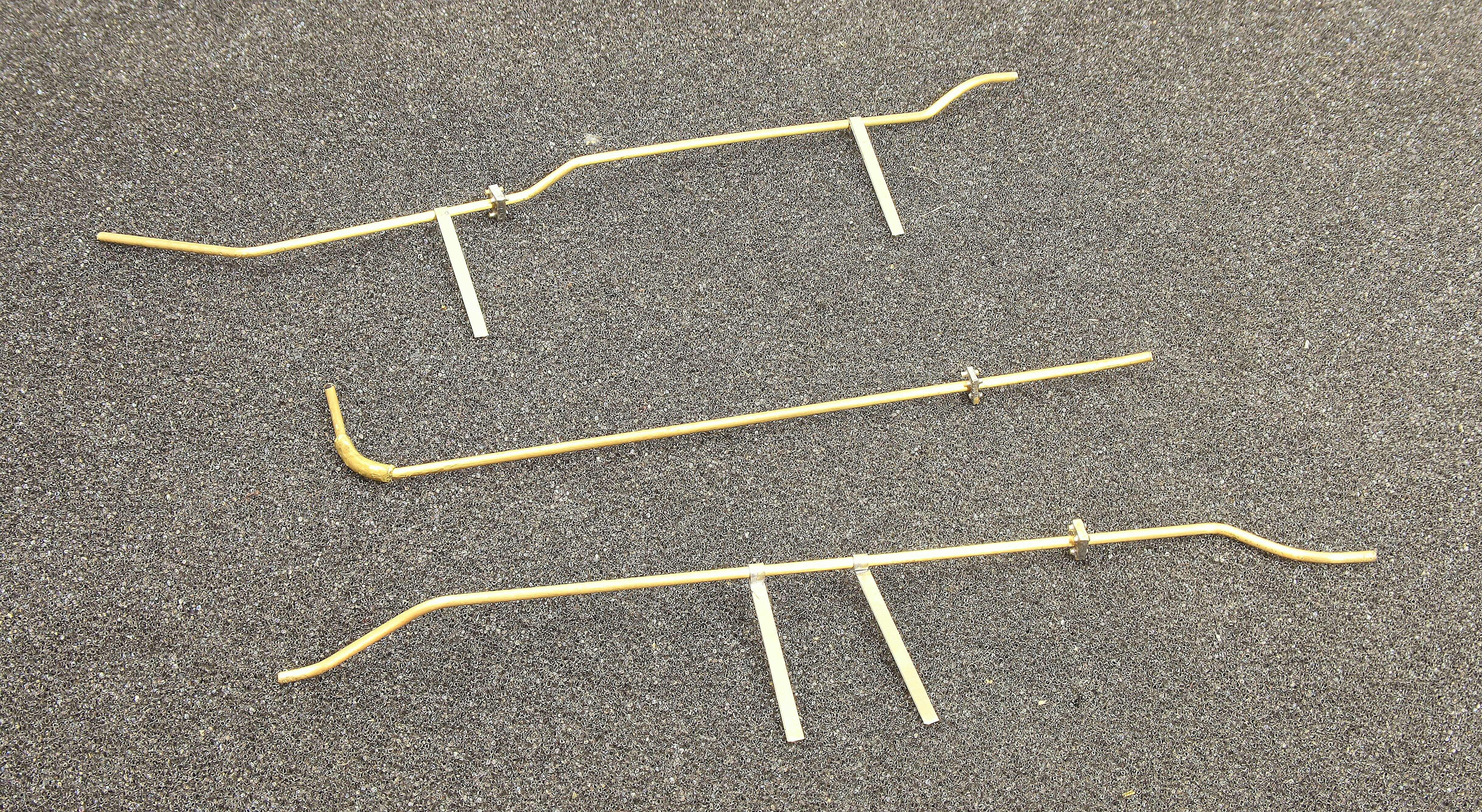
Finally for this update I chose what I viewed as the easier set of pipework to add first. Not before I replaced the etched mounting brackets with some from flat bar after peering at photos and noticing that they were plates with two holes in them rather than straps wrapped around the pipework.

53504937322_6792755f7d_h.jpg

Now to work out how to fit the injector pipe on the other side.
 

Rob Pulham

Western Thunderer
The Princess continues to challenge.

The replacement for the live steam injector pipe took much tweaking and test fitting before it fit snugly with the chassis in place.

53528839874_d68f361e64_h.jpg

Once I got my head around how the pipes ran, the two front oilers didn't present too much of an issue although I had to look at a good number of photos before I worked out where said pipes ran.

53528839859_4258b9ff58_b.jpg

53527624462_acaedace9f_b.jpg

Next I removed the pin rom the bottom of the steam pipe castings and drilled and tapped them 10 BA so that I could screw them to the footplate through the mounting holes

53528759663_ffb7c4f067_h.jpg

As can be seen from the snips below there is quite a gap between the boiler and the steampipe flange. At the moment I am not sure where the problem lies, whether it's in the placement of the mounting holes, in the dimensions of the castings or something else. Initially I tried turning down some washers to fill the gap but I don't think that's the answer.

53527758547_3545271149_b.jpg

53529083540_6bc2031292_c.jpg
 

simond

Western Thunderer
Rob,

in your photo of the real thing, the “fat cylinder” is fitted to, and tight on, the smokebox. The bent pipe is a “loose fit“ in the cylinder.

might you be able to do the same?

just looking at your pictures, the “fat cylinder” looks a bit longer in the real thing than the castings you have, maybe that’s where the missing bit should be?

atb
Simon
 

OzzyO

Western Thunderer
Hello Rob,

you have the drawings. So I'd check the length between the centres of the steam pipe, from the footplate to the entrance to the smoke box. You may have to make new steam pipes by cutting gashes using a V shaped cutter on it's side I'm not sure if Tony made patterns for the Princess steam pipes? If he did they could be in the Renalds range of castings. I can't remember who sells them.

Coming along nicely
ATB

OzzyO.
 
Last edited:

Hobbyhorse

Western Thunderer
Hello Rob,

you have the drawings. So I'd check the length between the centres of the steam pipe, from the footplate to the entrance to the smoke box. You may have to make new steam pipes by cutting gashes using a V shaped cutter on it's side I'm not sure if he made patterns for the Renalds range of castings.

Coming along nicely
ATB

OzzyO.
Tony didn't do any patterns for the outside steam pipes.
I've got two ways that I've used in the past with issues like this, it will be easier to talk about them on tonights Online Modellers Meeting.

Simon
 

Rob Pulham

Western Thunderer
Rob,

in your photo of the real thing, the “fat cylinder” is fitted to, and tight on, the smokebox. The bent pipe is a “loose fit“ in the cylinder.

might you be able to do the same?

just looking at your pictures, the “fat cylinder” looks a bit longer in the real thing than the castings you have, maybe that’s where the missing bit should be?

atb
Simon
Hi Simon,

According to the GA the fat cylinder is only 0.3mm shorter than the drawing suggests it should be on the surface. The washers which I tried in place to fill the gap are 0.7mm and they dont fill the gap on one side.

However because as you suggest, it's a sleeve and that sleeve passes through the smokebox then there will be variations on just how much protrudes out either side I am sure.

I am now exploring options as to how best resolve the issue. I am going to start with a 3D drawing and then work on to more traditional methods Which may involve a top hat type sleeve fitted from inside the smoke box.
 

Rob Pulham

Western Thunderer
Plan A is to recreate the flanged sleeve as a separate entity which will sip over the end of the main steam pipe and allow movement to hopefully take up the gap.

I started by fly cutting both ends of a piece of nickel bar to the radius of the smokebox.

53534419173_6365f848f3_h.jpg

Then, I turned down the diameter and drilled out the centres before parting them off.

53534292291_768e72a7f9_h.jpg

The backing disks were turned from small squares of 0.2mm thick scrap etch.

53534470988_69805fe978.jpg

The disks were turned, by super gluing the square offcuts to an arbor made from the remains of the nickel bar that the sleeves were turned from. I could have used solder to stick them to the arbor but reasoned that super-glue would be easier to get off the finished disks and so it proved.

53534553404_3353ae20c9_h.jpg

The next job is to remove the cast sleeves from the end of the steam pipe castings.
 

Rob Pulham

Western Thunderer
Removing the cast sleeve was a bit of a challenge and I used a combination of a piercing saw, a wood chisel and old files dipped in talc. This did remove the sleeve but it was hard work and left the stub slightly oversized and not remotely round.

I decided to make a tool to cut the stub into a regular round shape. I started with a length of steel round bar which I had recovered from an old printer fuser unit that I had replaced. I salvaged all the useful parts which included the bar, several springs and a number of screws. I am not sure what type of steel it is but it's probably the most free machining steel that have used to date.

I cut off a short length and faced off the end. Then I drilled a 3.2mm hole in the end. Once drilled I then took it over to the mill where I secured the length of bar in a square collet block. Finally using a bit of trial and error I cut teeth into the rim. The series of photos below show some of the milling process. I had already took a small cut to establish where the teeth would be before thinking to take photos.

53539067838_6c00650fd5_h.jpg

53539067588_33faf65dda_h.jpg

53539309305_57cab55062_h.jpg

53539309120_25c24f7a14_h.jpg

53538007542_b47548f411_h.jpg

53539210449_9204b304ac_h.jpg

The opposite end of the rod had a stub turned on it (which it located in the printer). This allowed it to be gripped with ease in a pin vice.

53539306145_79b71990b0_h.jpg

It made remarkably short work of truing up the misshapen end of the casting.

53539064338_f69bb17df8_h.jpg

53539067273_105e245b25_b.jpg

53538008837_18338d8a87_h.jpg

The next job is to test fit them to the footplate and see if I have resolved the problem.
 
Top