Finescale - of a sort?!

Peter Insole

Western Thunderer
Thank you so much Overseer, that is just the perfect answer!

Ha, ha, ha, it just goes to show how easily that howlers like this can occur! The impression given was that image attribution is from Trafford's own library and archive services?!!

Absolutely priceless!

Pete.
 
Last edited:

Peter Insole

Western Thunderer
While still in the questioning mode, here is another riddle that has been troubling me and I have been meaning to ask for quite some time:

When considering the subject of water level gauge glasses and their protectors, we normally think immediately of the familiar, three-sided glass variety.

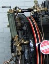
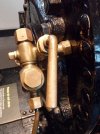
horwichwren vLancashire_and_Yorkshire_Railway_0-4-0ST_locomotive_WREN_(1).jpghzbhggSAM_3078.JPG

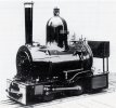
As you can see from the above, "Wren" (along with all the later Horwich survivors) had been thus fitted. Unfortunately, as a result of some "health and safety" considerations at the NRM, the protector (and rather strangely including the original top steam cock) have subsequently been removed. Despite the entire footplate now being enclosed with an acrylic screen, the items have not been returned - which may well indicate that they have since been lost?! Whatever the case, there is not much reference available there.

Having a reasonable understanding of how a gauge glass is assembled, and with no comprehension of any alternative method, I went ahead and copied the sleeve nut arrangement on the remaining bottom cock.

It was only later that I realised that the familiar protectors were a retrospective modification carried out by the LMS - whereas the original slotted tube type persisted throughout the LYR days!

Indeed, the glass box type are a relatively "modern" innovation, and as far as I am aware various patents weren't taken out much before the 1890's/early 1900's, and then it probably took quite a while before they became common currency?

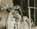
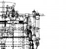
horwichwren u1c Fly LYR-class-Z-0-4-0ST-Postcard-Lancashire.jpghorwichwren uz18inch locos 560b.jpg

Quite apart from the notable variation between the official drawing, showing square bodies to the top and bottom cocks, compared with the actual prototypes, it also shows a slot only on the viewing side of the tube. I would have expected to see a corresponding slot at the rear in order to a provide a degree of illumination through the glass?

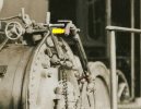
The detail photograph is the only reasonably decent one available, and does appear to show that last point, but I cannot be absolutely certain.

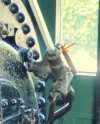
Unfortunately, "Dot" at Tywyn (in the view below) does appear to have original and partly plain sleeve type fittings, but yet again the tube protector has gone walkies!

peacockdot tp14715767744_35dbfcd67f_o.jpg

Careful study of both photographs has failed to reveal the actual method of fitting or removing that tube, as there just doesn't seem to be enough potential upward or downward movement available to clear the nuts, especially bearing in mind that those nuts will move towards the centre and reduce the clearance still further when being undone?!

OK., I know it would be so much easier to simply carry on with the glass box variety - and let's face it, the youngsters are more likely to recognise the later type anyway, but I am indeed a contrary soul, and would infinitely prefer to be correct. Besides, I cannot bear to be confounded either!

Does anyone out there have a drawing, diagram or any other reference material regarding the earlier fittings that might be enlightening?

I should have pointed out that the glass and shield on the model will have to be undone prototypically, as the only way to gain access to the electrics within is by sliding the complete firebox out of the backhead - and the gauge glass gets right in the way!

Many thanks in anticipation.

Pete.
 
Last edited:

Tim Watson

Western Thunderer
The gauge glass is removed through the top of the upper fixing, by removing the top bolt, Pete -visible in the Tywyn and L&Y pictures. My recollection of traction engine glasses is that the brass protector tube is a closish fit with a window to show the water level in the glass as appropriate. Most likely such a gauge glass could have e.g. a red stripe down the back of it to show the water level.

To assemble it the glass is fed through from the top fixing with a top gasket, top union nut, then protector, then bottom nut and associated gasket with the foot end engaging with the bottom fitting: does that make sense? The two union nuts are tightened up ever so carefully, hoping that one doesn’t here the tell tale ‘click’ of the glass cracking because you’ve overdone the tightening…

Tim
 

Peter Insole

Western Thunderer
Thank you so much Tim and Michael, that surely is the answer - and I've almost got it!

I was previously aware that the top and side union nuts were primarily for access to the valves and seats, but for the life of me just could not work out how the glass could be sealed with rubber "grommets" if fed through from the top!

My own top nut is threaded into a hollow valve body, so slipping the glass (or in our more child friendly case, clear acrylic tube!) in and out through there would be no problem.

I could even slip a simple couple of "O" rings in to stop the "glass" and protector tube from rattling around in service too?!

Pete.
 

Peter Insole

Western Thunderer
Question one, the laugh is very much on me! The correct answer has just been found!

qzzq broad gauge GSWR Class 52 ROYAL JUBILEE EXHIBITION MANCHESTER 1887 D5ueKPBWkAM6e5l.jpg

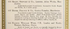
The full "Royal Jubilee Exhibition, Manchester, 1887 Catalogue" is available online, and the loco was exhibit number 1209, on page 230, in the "Irish section"!

Incidentally, Howard Grubb's observatory was no. 1234, and the Matthew Byrne bell foundry no. 1232!

The Irish presence at the event was admitted in the catalogue introduction to be a form of recompense for the fact that some terrible things had happened directly as a result of previous Manchester traders' determination to completely dominate and cripple their main competitors!

I am sorry if that sounds too political, but that was the reason given!

Pete.
 

Overseer

Western Thunderer
Question one, the laugh is very much on me! The correct answer has just been found!

View attachment 172778

The full "Royal Jubilee Exhibition, Manchester, 1887 Catalogue" is available online, and the loco was exhibit number 1209, on page 230, in the "Irish section"!

Incidentally, Howard Grubb's observatory was no. 1234, and the Matthew Byrne bell foundry no. 1232!

The Irish presence at the event was admitted in the catalogue introduction to be a form of recompense for the fact that some terrible things had happened directly as a result of previous Manchester traders' determination to completely dominate and cripple their main competitors!

I am sorry if that sounds too political, but that was the reason given!

Pete.
Good research. I had tried to confirm if it could have been Dublin in 1907 and decided probably not. The Dublin exhibition was even more political, with calls from the Irish Nationalists to veto it for displaying foreign products. The French had a large presence, all presented in French even in the catalogue. I found a letter published in a NSW regional paper from one Geoffrey Prendergast, student at All Hallows College, Dublin describing the Dublin Exhibition, including “All the shipping companies exhibited models of their best and largest boats. Even the Medic was represented. Then there were electric tramcars, ready for work on the streets, and there was also an express mail engine and set of carriages. An engine driver was always there to show anyone the workings of a railway locomotive.” Not conclusive.

The Dublin 1907 catalogue is also available online, the loco present was a Great Southern & Western Railway "Six coupled Bogie Goods Engine and Tender". Almost certainly a Coey 4-6-0 built from 1905, so too modern for the loco shown in the photo. They also showed a Third class bogie carriage, while the Great Northern had a bogie corridor composite carriage, the Midland Great Western showed a bogie saloon carriage and the Dublin and South Eastern showed an 'Old open carriage, built in 1837 for the passenger carriage between Dublin and Kingstown." I wonder if it was still standard gauge?

And just for a little Western content, one of the advertisements in the catalogue.
dublin 1907 hurst nelson.jpg
 

Peter Insole

Western Thunderer
This is indeed proving to be a wonderful diversion, (rabbit hole) and the sort of thing that I enjoy so very much!

Here is a bit more - albeit referring to an earlier post of mine, but nonetheless connected by the newly found catalogue entries:

royaljubileeexhi00roya_0157.jpg

Please note the last line regarding "Dot" (entry No. 637):

"...and also adapted for tail rope shunting..."

No such "adaptation" was ever carried by the Horwich engine of the same name - nor indeed any of her sisters either. However dear friends, do take a closer look at Beyer Peacock's own version:

rpeacockdot b192.jpg

Observe the unique drawbar, with a turned back hook arrangement, that was not specified on any of the surviving Horwich drawings, nor do any photograph show anything similar.

That surely is the special "adaptation" mentioned in the contemporary description. By also taking into consideration the additionally ornate chimney cap (purely for exhibition purposes?) it does rather beg the question of which engine was actually present at the 1887 show?

It might also be worth considering that a manufacturer's order number was a paper exercise - and should not necessarily be taken as evidence of the actual build or completion dates! A busy railway works that was kept fully occupied with multiple contracts, where the modern idea of production line techniques had yet to be fulfilled would mean that various jobs were more likely have been put on hold from time to time to allow the best utilisation of a highly skilled workforce.

If the Beyer Peacock records are to be trusted, (I can see little reason not to) and it was the Horwich engine that attended, the evidence presented here, along with the otherwise peculiar decision to simultaneously provide two locomotives with the same name, might then suggest that my original assertion that the parts were swapped after the exhibition was correct, and that there was an intended degree of deception involved?!

What does the respected jury think?

Pete.

(copyright images shown for illustrative purposes only.)
 

Peter Insole

Western Thunderer
Returning to the purpose of the thread and the most important question, (while being mindful of not causing any offence!) ;) after much thought I realise that I am still not sure about the answers so generously provided!

Tim, your comment that you feared hearing a crunch of fracturing glass when tightening up is covered in at least one engineman's manual, in that there is an annular stop in the bottom cock to ensure that the glass is correctly positioned - but when installing, the tube should be pushed down to that stop and then lifted back up by a measured amount before tightening the gland nuts, thus ensuring "that under no circumstances should the glass become in contact with any part of the metal cock". If the gauge uses the conventional design of having rubber seals that are compressed onto the outside of the glass tube by screwing down the gland nut, it should not actually be possible to over tighten it. Overcoming the mass of the contained rubber would require significant effort to be applied well before the glass fails.

I cannot work out how a glass tube could be fitted into any type of gauge that uses end "gasket" seals - without causing a potential obstruction to free flow of steam and water within the chambers of the top and bottom cocks? I am obviously missing something here?!

Michael, your book illustrations show a number of "one piece" or assembled gauges recommended for model engineers, but one feature is common to all of such types is that they can only be fitted with integral flanges over studs on the boiler! Our little engine has no room for such flanges, and both the threaded top and bottom cocks have to be independently rotated into tapped holes in the turret and backhead respectively.
This latter point means that a tubular "protector" has to be readily removable.

My problem still exists! Careful examination of the drawings and photographs, such as they are, fails to show sufficient upward or downward movement of the protector tube to allow it to clear the gland nuts for installation or subsequent removal, let alone what method of securing the glass seals was required?!

The fitting design on these engines was at one time of common practice and could almost be described as standard before the more familiar "box" type was introduced, which is why the difficulty of obtaining reference is so frustrating!

The solution is likely to be devastatingly simple and should be perfectly obvious - it is just that I can't see it for all the looking!

Pete.
 

simond

Western Thunderer
Pete,

I don’t know the answer but will offer a hypothesis:

the glass is secured to the end collars by a gland nut that surrounds the tube and the rubber sleeves that are compressed onto the glass. I guess this is done whilst the end collars are secured to the shut-off cocks at each end. The hex head on the top (and I suspect it’s mate at the lower end) appear to be banjo “bolts”, and they are then removed, the glass-and-end-fittings removed, the sleeve fitted over the glass, the assembly re-installed and the end fittings re-secured and sealed with the banjo bolts again.

Whilst this is feasible, and there is a visible discontinuity between the collars surrounding the glass and the end fittings which would be in the right place, it’s far from an elegant solution, so I’m not convinced, but maybe?
 

michael mott

Western Thunderer
Peter Thinking about your problem can you overcome your assembly problem bu using a similar method to that used on some door handles like this picture where you wind in your stub bar that is solid then slip over it the complete assembly both at the top and bottom.

water glass.jpg
 

Peter Insole

Western Thunderer
Thank you for your thoughts, Simon and Michael. I agree that a banjo at the top (the bottom leads straight into the blowdown valve) would seem the most likely, but as you say, an inelegant solution. I still wonder about the use of such a fitting, especially bearing in mind the well documented need for a free flow of steam and water at either end of the glass - and the consequences arising from even relatively minor restriction?! I have no doubt that the arrangement is the only possible option for a one-piece gauge in a live-steam model locomotive.

That is a good idea Michael, and as you may have already noticed I am not at all averse to ending up with subtle, (?) craftily concocted (??) wheeze solutions (???)! I think something along those lines might be necessary with this one!

It is just a shame knowing that hidden away in a cabinet, file box or dusty book somewhere is a sectional drawing showing exactly how the prototype was arranged, and that seeing it would undoubtedly provide me with another set of problems to bodge my way around!

Pete.
 

Tim Watson

Western Thunderer
Tim, your comment that you feared hearing a crunch of fracturing glass when tightening up is covered in at least one engineman's manual, in that there is an annular stop in the bottom cock to ensure that the glass is correctly positioned - but when installing, the tube should be pushed down to that stop and then lifted back up by a measured amount before tightening the gland nuts, thus ensuring "that under no circumstances should the glass become in contact with any part of the metal cock". If the gauge uses the conventional design of having rubber seals that are compressed onto the outside of the glass tube by screwing down the gland nut, it should not actually be possible to over tighten it. Overcoming the mass of the contained rubber would require significant effort to be applied well before the glass fails.
Absolutely essential that water the passages are kept clear. However, the torsional loads and grip from O rings (or similar) is easily able to crack the glass when the gland nuts are tightened - at least in a 1/3 scale miniature traction engine. It’s not a graunchy noise, just a little ‘click’.

Cylindrical brass gauge covers could be made by two hemispherical pressings that lock and bolt together.

Tim
 

michael mott

Western Thunderer
Pete, Looking again at the photo Perhaps there is only a banjo fitting at the top. The bottom valve wound in first then the Brass sleeve and glass wound in to the bottom valve but not fully in line with the top valve yet, then the top valve wound in, then the bottom valve and glass assembly finally lined up then the nut to seal up the banjo.

This all sounds too complex indeed and that is probably why they used flange fittings on the real thing.

Michael
 

class27

Active Member
I guess a real Gauge glass on a Fullsize loco would be quite a strong bit of kit. Just thinking about Gas Meter Sight glasses on network connections that see about 650 psi.
Moncrieffe's Glassworks, (Monax) in my home town of Perth, were world famous for them many Years ago. Sadly one of the many sites I De-commissioned in my tenure
 

Pete_S

Active Member
Whilst demonstrating fixed installations, I suspect the process is likely to be identical:—


The earliest railway source material I have to hand is "Locomotive Management from Cleaning to Driving" by J.T. Hodgson & John Williams (4th Ed. 1920)

FROM THE WELL-KNOWN FACT that one of the most common causes of boiler explosions is shortness of water, it will be readily understood that the water gauge fittings on the front plate are very necessary adjuncts to a boiler. Two sets of gauge glass fittings are usually employed, so that one acts as a check against the other, and as a safeguard should one require repairing or not be working properly. The glass tube water gauge consists of a straight glass tube connected by suitable fittings at the top end to the steam space in the boiler, and at the bottom end with the water, the bottom end of the glass being fixed above the highest part of the heating surfaces. The gauge glass is a simple and yet effective method of showing the water level, the steam being transparent in the glass, and the water rising to its own level in the boiler. One of the principal objections to the use of gauge glasses is the chance of injury to the driver and fireman by the bursting of a glass. This objection is now overcome by the introduction of gauge glass fittings containing balls or valves, which automatically shut off the steam and water when a break or burst occurs, and by the adoption of plate glass and other protectors to arrest the flying pieces of glass.

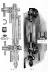
Dewrance and Co., London, are makers of the gauge glass fittings, with automatic ball and valve arrangements, as shown in the sectional view, fig. 29. In the event of a gauge glass breaking under pressure, the ball in the lower arm rises to its seat and cuts off the rush of scalding water. The upper arm is also rendered automatic in action by means of the patent spring valve, which is closed by the sudden rush of steam when the glass tube breaks. The spring is made of a special quality of bronze that is not injured by steam at 300 lbs. pressure and is strong enough to keep the valve from closing, when blowing through in the ordinary manner.

Gauge glasses and fittings have been so improved in recent years that breakages are reduced to a minimum although when a burst does occur, the fragments fly in all directions, and many men have lost their sight through injuries received in this way. Messrs. Dewrance were the first to introduce the patent gauge glass protectors (fig. 30) for the prevention of such accidents. The glass plates forming the front and sides of the protector are specially toughened, and every plate used is properly tested to ensure that it will withstand the shock of a gauge glass bursting under the highest working pressure.

FALSE READINGS of the water level will be given should any scale or obstruction be lodged in the orifices leading to the boiler, and on this account the glasses should be blown through occasionally. This is done by closing the middle cock and opening the lower one; the top one being left open, steam will be blown downwards through the glass tube, after closing the top cock, open the middle cock, thus clearing the water passage leading to the gauge. The action of the automatic valves or balls in shutting off the steam and water, when a break occurs, will be considerably interfered with if the passages leading to the gauge glasses are allowed to become choked with scale or dirt.
Some boilers are fitted with test cocks in addition to the gauge glasses, but it is the glasses that give the driver and fireman the greatest sense of security and satisfaction on account of the water level being so readily seen.

BY WATCHING THE GLASSES the fireman can fire according to the rate at which the boiler is feeding, and this, coupled with a knowledge of the gradients and stops, goes a long way towards economical working.
The boiler corrosion, or soda, etc., in the feed water gradually deteriorate the glasses, and these should be changed before their limit of endurance is reached.
A glass that is giving out will show signs of flaws and streaks at the upper end, and with practice these can in many cases be detected when they appear.

MANY GLASSES ARE BROKEN by improper gland packing setting up strains, which ultimately shorten the life of the glass. In fixing a new one it should be seen that the gland nut is 1/8 in. larger in diameter than the outside diameter of the glass, and that the glass tube has at least 1/8 in. end play to allow for expansion.
Various materials are used for packing the glands, the best being that which tightens home with little pressure, such as good fitting rubber rings, or asbestos cord evenly wrapped round. Hard substances, such as hemp, etc., should not be used for this purpose, because a fairly large amount of pressure is required to make them steam-tight.
In tightening up, turn the top and bottom nuts alternately so that each end of the glass is secured evenly and without undue strain. With a well-packed gland a steam-tight joint should be made by simply screwing up the gland nuts by hand, and, if the glass cannot be easily turned, it may be taken for granted that the gland is improperly packed, or that the gauge fittings are out of line.

071.jpg

Pete S.
 

Peter Insole

Western Thunderer
Thank you so much for your reply Pete S. That is the best illustration of the Dewrance (Wall's patent) gauge yet, and the text and video confirm what I had previously found, that hand pressure only on the gland nuts should be sufficient to obtain a firm and pressure tight seal!

That last point may explain why the main body of the original gland nuts on the Beyer Peacock and Horwich engines was a smooth cylinder. The very small hex section at the top (which also appears to be separate in the photo) is almost certainly a variant of the Dewrance gland, and has the external facility of being freed with a spanner only in the event of it becoming jammed, presumably something that might potentially happen after a glass breakage?

zmwater horwichwren-peacockdot tp14715767744_35dbfcd67f_ob.jpg

The later, (LMS) and indeed the more or less "standard" use of a large hex exterior for gland nuts favoured elsewhere, seems to be a bit of a daft idea - and an almost open invitation for enginemen to grab a big spanner and seriously overtighten the nuts!!

Another interesting feature revealed by the illustration is detail of the "safety" ball arrangement in the lower, water cock. It's fitting requires a longer body to the valve than the Beyer Peacock and Horwich type, and notably, a large enough cap nut to accommodate it. Having already studied the remaining fitting on "Wren" and made up both top and bottom cocks on my loco, it is quite clear that no ball type fitting was ever used. The LMS did fit later pattern protectors, but the original (risky!) cocks were retained!

That lack of a safety feature, plus the exposed glass section of the original tube type protector, might explain why the viewing slot has been turned to awkwardly face downwards in the old photo of "Fly". I wonder if there had been a previous accident at the works, and the image reveals the remedial action thus adopted?

By the way - and this is not meant to be either an insulting or controversial statement - I have noted during the course of this research that the dear old GWR stubbornly persisted with their own version of the (dodgy) tube type protectors right to the very end - although they did provide longer and combined levers to allow a critically wounded crew to shut the valves off at a slight distance from the source of their agony!!

Pete.
 
Last edited:

Peter Insole

Western Thunderer
Trying to work out how the old tubular protector could possibly lift out with the glands and nuts getting in the way has been an interesting journey, but as I suspected, the solution was indeed a simple one staring me in the face!

I could not have got there without help though, and I really do appreciate all the assistance so generously provided!

The peculiar problem was based on the predication that the gland nuts had to be tightened firmly down onto the packings with a spanner... and why wouldn't that be the case? I continued to ignore the repeated message that if the packings are properly aligned only hand pressure was required to ensure a good seal. Re-reading that last document and finally recognising the important point that the glass had to be capable of being rotated in the seated packings was the dawning moment!

The "gunmetal" tube protector only needs to slide up or down (after slacking off the single grub screw at the base) sufficiently to gain a firm grip on the gland nut shanks to undo them, push them further up inside the protector tube and the whole thing can then be lifted out unobstructed from between the cocks!

Now all I have to do is get the jolly files out again...!!

Pete.
 

Peter Insole

Western Thunderer
Well, it has been a while since I last posted on this thread, but I had been concentrating mainly on the railway extension, although for the last few weeks another bout of illness has kept me from any other activity.

The "little engine" does need some essential work on both the mechanicals and electrics, issues that have been especially highlighted by operation on the new loop! With the machine being our only motive power at present, I have been restricting it's use and keeping a very wary eye on the problem areas when running was called for! I had hoped that the new "Speeder" would be a fairly straightforward and temporary replacement for this summer season, allowing me to wait until the coming winter to carry out a thorough overhaul, but circumstances have conspired to cause some delay!

Now that I am recovering, I feel ready to start again. Several and various parts have been ordered for both locomotives, but as they are coming from different sources, the delivery is a bit awkward and erratic! While waiting for key components to turn up, I have decided on a change of plan, and make a start on dealing with the most pressing issue on the engine:

Quite some time ago, I had spent far too long worrying, and not enough doing about the odd. plastic driving wheels. To date, they have worked surprisingly well, but there is clearly a weakness at the original, 8mm bore hubs on the leading pair. I was torn between home-made remedial measures, or replacing the whole shebang with "proper" steel wheels all round! It was not so much the cost of the suitable four and a half inch, plain disc wheels, (then at £14 each) but the prospect of having to ask for assistance with machining them for new crankpins and making collars for fitting on two different diameter axles! I had got as far as acquiring a pair of pillow block bearings, some rod and tube, plus 12mm bore flanges and four flat steel discs (cut to my specified size) for a "bodge" job on the existing arrangement, but ended up putting the cache aside for a later date!

While assuming that the SMR Engineering, 7 1/4 inch, Narrow Gauge profile wheels (now £17 each) might be appropriate, I could not be absolutely sure. A couple of days ago, I decided to cut out a full size template - albeit slightly roughly (!) - just to check...
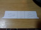
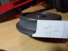
SAM_yx8997.JPG
SAM_yx8996.JPG

It is a bit of a "no-brainer" isn't it?

To quote a friend; "At that price, it is almost an insult not to buy!"

Such good value is not likely to last for much longer I fear, so as soon as funds permit, I will go ahead and order!

Even if I do manage to obtain a set before the end of next month, I would still like to allow plenty of time for setting up. A straight swap is not really practical, so I have decided to carry on with the original idea. At least I will still be able to run trains on the railway for the remainder of the season!

One thing that the terribly sharp curve has regrettably revealed is the desperate weakness of my original front end suspension...
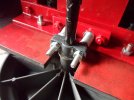
SAM_yx8993.JPG

It had been absolutely fine on the gentle curves, but on the loop, excessive play fore and aft was allowing the axle to twist in between the quartering strokes. The "creep" friction was trying to turn the axle into the curve!

Despite the appalling stresses such a hammering effect was having, I was utterly astounded by how little wear was showing in the bare coupling rod bearings when I took down the motion - especially considering the mileage we have been clocking up!

Even though I had always preferred the idea of fitting sealed ball races in the big ends later, it would almost seem as if any concerns I might have were quite unfounded, and perhaps bearings might even be an unnecessary luxury?!
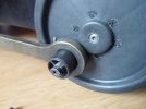
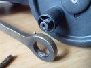
SAM_yx8990.JPGSAM_yx8992.JPG

For the new (temporary) repair work, I shall be perfectly happy to keep the old arrangement just as it is - albeit re-set on new metal crankpins for the rear driving wheels!

As planned, I have cut away the old hubs and removed the original large crankpins to provide completely flush wheel centres - over which I can then fit the new steel discs...
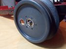
SAM_yx8994.JPG

Just to show how peculiar I am; I have centred, drilled, tapped and fitted the crankpins on the leading pair of discs before doing the rears (already prepared) - so hey-ho, there you go!
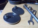
SAM_yx8999.JPG

The 12mm bore flanges will be fitted to the back of the discs with machine screws, tapped and driven from the rear, with their ends filed flush, and hopefully almost invisible on the outer face once painted?!

When set up on the axles, I will similarly fit more screws through the plastic wheel centres, this time with large washers in the segments between the hidden "spokes" to firmly fix the whole assembly.

One nice feature of the finished job will be a much more accurate appearance to the wheelsets - with the centres flush with the axle ends and tyre rims, save the narrow recess all round.

It should all keep me busy for the next few days - and get the trains running again - for a wee while longer anyway!

Pete.
 

Peter Insole

Western Thunderer
Progress is happening, but plodding! I am still severely restricted to just a couple of hours in the afternoon for any noisy workshop activities - so I am champing at the bit a bit!

Centre punching, drilling, tapping, sawing and filing off ends of a mass of studs is going to have to wait until later!

I am quite pleased with yesterday's session on the first wheel - I have just got to repeat it, and then some for the other one.

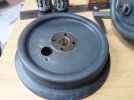
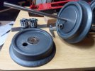
hSAM_yx9001.JPGhSAM_yx9000.JPG

I found a most convenient - and yet again a rather jammy way (although not too neatly) removing the original plastic hubs:

A hole saw from my box of bits just happened to fit perfectly over the raised hub on the outer faces of the wheels, while the guidance bit was also the right size to run down the original bore. What is more; the finished hole in the wheel was not only guaranteed to be central, but turned out to be a superbly snug, press fit for the new, metal flanges!

Unbelievable luck!

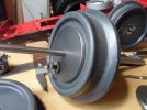
hSAM_yx9002.JPG

I am using an 8mm diameter rod to hold the disc centrally over the flange to get the four screw holes accurately punched for drilling through.

The good fortune was bound to run out though?

hSAM_yx9004.JPG

I have no idea what the flange manufacturers were thinking, or indeed what type of fitting it was intended for?

The holes are plain bore, and definitely M4, but are set much too close to the flange shoulder to accommodate any form of screw head or M4 nut! I was left with no choice but to whizz down the diameter of the smallest cross-heads I could find.

It is a bit of a nuisance having to faff around with unexpected hiccups like that, but the eventual assembly, whist not the prettiest solution, is now nice, sturdy and hopefully up to some more rough and tumble out on the road!

Pete.
 
Top