You are using an out of date browser. It may not display this or other websites correctly.
You should upgrade or use an alternative browser.
You should upgrade or use an alternative browser.
Giles' misc. Work bench.
- Thread starter Giles
- Start date
Rob R
Western Thunderer
Simon,
Measured in time, layout miles or drops to the floor?
In reality, at the moment there are too many variables (resin type, correct exposure or not, correct curing or not, excessive press fit onto the axles etc) and insufficient data out in there. Just suck it and see, apply sound engineering principles and don't drop it!
Rob
Measured in time, layout miles or drops to the floor?

In reality, at the moment there are too many variables (resin type, correct exposure or not, correct curing or not, excessive press fit onto the axles etc) and insufficient data out in there. Just suck it and see, apply sound engineering principles and don't drop it!
Rob
SimonT
Western Thunderer
I ran a 57XX with printed coupling rods for the best part of a year. They had brass bushes and pins and there was no wear. (The bushes were a press fit) Eventually they were failed by a piece of outragious clumsyness. They did the job and best of all an expert told me that they wouldn't be strong enough to do the job. I would quite happily do it again using one of the high strength resins from Formlabs. Only problem is the price for a litre of resin and a tank for it.
Happy New Year
Happy New Year
Last edited:
ianlbsc
Western Thunderer
I have some that are from Elegoo standard resin, been on an inside, east facing window sill for over three years now, unpainted, and showing no signs of deterioration.Do we have any idea of the life expectancy of 3DP parts?
Giles
Western Thunderer
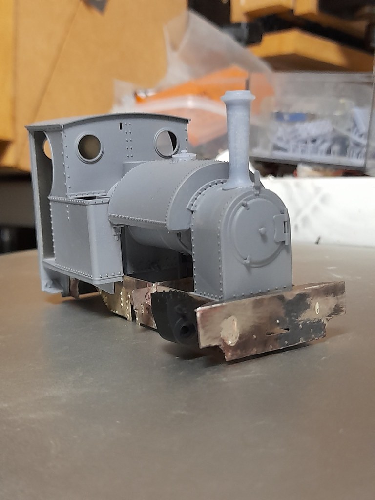
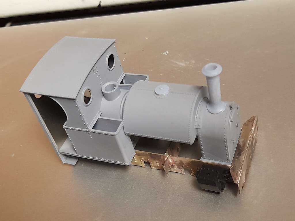
I've started to work out the chassis, and cut the two frames on the Stepcraft (and blind drilling the rivets in the process, ready for embossing). I still have the front buffer beam stretchers etc to do. Cylinders and steam brake plug in perfectly, which is nice....
Giles
Western Thunderer
I now have the basic chassis. This is CNCd, but the data is good for any other technique. I have silver soldered this, as is my preference, but still to be added is the angles to the top of the frames and the front buffer beams. Similarly, slide bars will need soldering on to the motion brackets...... After this, all the printed detail can go on. Cylinders, brake stuff, springs etc....



adrian
Flying Squad
Very nicely done - are you silver-soldering nickel-silver? I have thought about it for frames in the past but various people reckoned it wouldn't work as the heat would distort the frames. Your work seems to disprove that.I now have the basic chassis. This is CNCd, but the data is good for any other technique. I have silver soldered this, as is my preference, but still to be added is the angles to the top of the frames and the front buffer beams.
Giles
Western Thunderer
Yes - so far that chassis is all silver soldered N/S. Used judiciously I've had no problems. What I wouldn't do is to try to silver solder the reinforcing angles over the length. That is certainly likely to induce problems - but buffer beams, stretchers, motion brackets and the like I certainly get away with, and it means I can soft solder the other stuff with impunity.
Giles
Western Thunderer
Having added the compensation bar which I had forgotten - I have added things like the springs now the soldering processes are hopefully complete.......
I have also been struggling with how to sensibly and affordably hold the wheels for boring centre's true. Finally the penny dropped, and I printed my own collets
I have also been struggling with how to sensibly and affordably hold the wheels for boring centre's true. Finally the penny dropped, and I printed my own collets
JimG
Western Thunderer
I have also been struggling with how to sensibly and affordably hold the wheels for boring centre's true. Finally the penny dropped, and I printed my own collets
Giles,
I might try that myself. I've been using a split chuck in my three jaw but found that it was giving me 3 thou + TIR. I am just about to make another split chuck, but maybe I'll try printing a step collet as you have done. The problem might be that the spindle taper in the Cowells is 0MT which is a bit small. The ML10 in the garage is 2MT but it's too cold out there at the moment.

How did you orient your collet in the slicer?
Jim.
David Halfpenny
Western Thunderer
Simon,I printed this (binnacle) yesterday, I could have turned it from wood and brass, and it might have looked better, but it's going inside the wheelhouse of the puffer and was simply never worth doing "the proper way" as it would have been a massive amount of work.
This puffer winch might interest you, as it's making offers a Third Option, namely making things "the proper way", but with cheap and speedily-worked PLA:
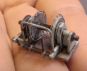
To give a sense of just how small it is, here are components in progress on fingernail - probably a small one, as its owner is a Korean woman - maybe 10mm diameter max:
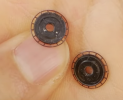
These components began as PLA filament, here being laid down with a 3D Pen:
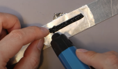
While still molten, the PLA was squished into a flat sheet between two rulers, then worked like Plastikard.
The fine rods are made by heating and stretching 1.75mm stock. Fatter rods are cast by squirting the 3D Pen into a tube, parts are bent using heat, carved using heat and burrs, and turned using either a mini-drill or a £30 Chinese lathe.
A benefit of this approach is that most regrets, mistakes or omissions waste far less material than they would on a 3D printed Monolith
 Though the Monolith will always win for Multiples
(I know none of this belongs on Giles's Workbench - I'm just sympathetic to Simon's dilemma.)
For more 3D Pen mastery - including sculptures as well as the complete ship and a BMW motorcycle, look up Hoo's Mini World
David
JimG
Western Thunderer
Giles,I've tried the printed chucks in the lathe, and been very pleased with the result......
I had a go myself to see what success I might get. The Cowells has a 0MT in its spindle and it's actually about half the length of a full 0MT taper. I also have a resin printer, so using a different medium.
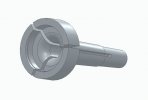
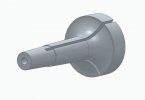
The step chuck as drawn in Solid Edge.
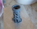
It was printed on end with the stepped end uppermost and the bottom directly on the build plate. The supports were added, primarily to provide a larger foot area on the build plate in case the increased diameter of the chucking end created too much pull for the smaller diameter end on the build plate.
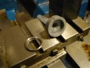
The printed step chuck on the lathe cross-slide with one of the wheel tyres to be used with it.
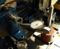
The step chuck is now in the spindle and I'm trying the dial gauge on the steel tyre to see how good it is - on this test 0.001" TIR which is way better than I expected. I thought if I got 0.002" - 0.003" TIR that would be good. Slaters commercial S scale wheels are typically to that TIR.
I furnished a 2.3mm hole in the inner end to be tapped 6BA for a drawbar - the resin doesn't lock in the taper. So that will be the next job to do but the workshop is in the middle of a major re-jigging at the moment so I'm not quite sure when I can continue with the experiment.
But thanks for the pointer to a solution to my problem.

Jim
