You are using an out of date browser. It may not display this or other websites correctly.
You should upgrade or use an alternative browser.
You should upgrade or use an alternative browser.
Ian_C's workbench - P4 and S7 allsorts
- Thread starter Ian_C
- Start date
Threadmarks
View all 177 threadmarks
Reader mode
Reader mode
Recent threadmarks
Bradwell WD 2-8-0 - working valve gear and motion, springs, brake shoes Bradwell WD 2-8-0 - Brakes that really do bring you to a stop... Bradwell WD 2-8-0 - injectors (welcome back threadmarks) Bradwell WD 2-8-0 - sanding gear Bradwell WD 2-8-0 - big bits coming together at last The 'no update' update Another no-upate update - and season's greetings Some kind of an update... NewDave Holt
Western Thunderer
Don't take any notice of my recommendations! Managed to snap off my 14 BA tap, yesterday, whilst tapping the bore of some tube that I'd drilled to 0.8 mm. The tap jammed and in trying to free it, I think I must have applied some bending moment and snapped it flush with the end of the job. Perhaps 0.85 mm would have avoided the problem? It had survived for about 20 years, so perhaps the tapping size drill isn't too tight.
Dave.
Dave.
Ian@StEnochs
Western Thunderer
Brass tube is not the easiest metal to tap. It tends to tear rather than cut cleanly. I have used it to make spacers for brake hangers, tapped 10BA, but I drill it 1.6 for tapping size 1.4. Still gives enough thread for the job.
Ian.
Ian.
Don't take any notice of my recommendations! Managed to snap off my 14 BA tap, yesterday, whilst tapping the bore of some tube that I'd drilled to 0.8 mm.
Dave.
Hi Dave,
If your tap lasted 20 years, your recommendations must be fine! Probably this was an-end-of life fatigue failure!!
I agree with Ian that brass can be a pain to tap because it is often quite hard and - in tube form - the grain runs the wrong way. One suggestion is that the job might be easier if the tube is anealled first. But experimentation can be expensive...
I wonder if, with the demise of your tap, it might be cheaper to move to M1 for the replacement? Last time I looked, both the taps and the fastenings are about 40% cheaper?
Best Wishes,
Howard
Bradwell WD 2-8-0 - the motor arrives, further complications, the drive train is assembled
Ian_C
Western Thunderer
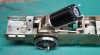
The motor from High Level dropped through the letterbox this morning. It's a nice little thing. It runs very smoothly and quietly on straight DC. The 'worm between finger and thumb test' shows it has plenty of torque for its size. At the very lowest speed there's some cogging evident, as you'd expect, but that smooths out when there's a little load applied. I haven't tried it on DCC yet, but I will at some point. Altogether a splendid little motor, and I can see it'll suit some other projects in the queue as well.
The motor comes with some M1.4 screws to hold it to your motor mount, but they're very short and only suitable for a sheet metal mounting. I had some M1.4 x 3 screws that were nearly long enough to work with my motor mounting block. Nearly. I had to make the counterbores in the mounting block a further 0.5mm deeper before I could fit the motor. Mercifully the calculated motor shaft to worm gear centres were spot on, so the gearbox was assembled as a trial.


Don't worry, the drivers aren't fixed to the axle and quartered yet, that's load of faff and another story that'll get posted here shortly. It all runs smoothly and quietly under power and there seems to be plenty of tractive effort at low speed.
Since the driven axle is suspended, the motor and gearbox need some kind of flexible torque reaction mounting to the chassis that accommodates vertical, lateral and rotational movement of the axle, but provides a close constraint on fore and aft movement of the gearbox. This is how it worked out...

The torque reaction link (blue) is fixed to the gearbox using an extended screw in the motor mounting block. The other end is fixed to a bracket (green), which in turn is fixed to a chassis crossmember. This crossmember ends up covered by the front of the firebox so the bracket is not visible when the upper works are installed. To provide the flexibility and constraint the link sits over tiny rubber bushes (purple). Solid brass 'top hat' bushes sit inside the rubber bushes and provide the connection to gearbox and chassis. The rubber bushes are small slices of silicone rubber tube of 3mm O.D. and 2mm I.D. The link holes and the top hat bushes are sized to be a snug fit in the rubber. The rubber provides the necessary compliance and some sound deadening.
It'a a performance and a half to get all this assembled to the chassis, but it does all go together...


The firebox and boiler can be assembled over this, and it all seems to clear. Frustratingly I can't see how close the motor is to the inside of the firebox, but I expect I'll find out soon!
A note on assembly. Even with a small motor (this one is 12mm diameter) there's no way to pass the motor through the chassis from below. The clear width inside the rear axle horn guides is a measly 9.8mm, and I don't fancy cutting back the horn guides and bearing blocks at this stage. Also as the wheels will be permanently fixed to the axle, all the gearbox gubbins is trapped on the axle forever, and that clearly has to be assembled to the chassis from below. The screws holding the motor to the the gearbox can't be accessed when the gearbox is assembled. The screws holding the torque reaction bracket to the chassis can't be got to when the motor is in place, and the chassis side prevents access to the forward link bush. Almost snookered.
The only way to do this is to assemble the torque link to the chassis bracket, and then the chassis bracket to the chassis. The gearbox is assembled, the axle fitted and the driving wheels quartered, gauged and fixed The axle and gearbox assembly is fitted to the chassis from below, without the motor. The motor mounting block is then removed from the gearbox and fitted to the motor. The motor and mounting block can then be fitted back to the gearbox side plates in-situ, and the rear fixing for the torque link assembled at the same time (there's only just access to the lower motor mounting block screws with the axle bearing at the top of the horn guide slots.
The only other way would be to assemble the motor and gearbox, minus the axle, and drop them into the chassis from above. Then attempt to thread the axle through everything and get the wheels gauged and quartered with the chassis all tangled up with the GW wheel press and the B-to-B gauge. Never a happy ending in my experience.
The motor comes with some M1.4 screws to hold it to your motor mount, but they're very short and only suitable for a sheet metal mounting. I had some M1.4 x 3 screws that were nearly long enough to work with my motor mounting block. Nearly. I had to make the counterbores in the mounting block a further 0.5mm deeper before I could fit the motor. Mercifully the calculated motor shaft to worm gear centres were spot on, so the gearbox was assembled as a trial.
Don't worry, the drivers aren't fixed to the axle and quartered yet, that's load of faff and another story that'll get posted here shortly. It all runs smoothly and quietly under power and there seems to be plenty of tractive effort at low speed.
Since the driven axle is suspended, the motor and gearbox need some kind of flexible torque reaction mounting to the chassis that accommodates vertical, lateral and rotational movement of the axle, but provides a close constraint on fore and aft movement of the gearbox. This is how it worked out...
The torque reaction link (blue) is fixed to the gearbox using an extended screw in the motor mounting block. The other end is fixed to a bracket (green), which in turn is fixed to a chassis crossmember. This crossmember ends up covered by the front of the firebox so the bracket is not visible when the upper works are installed. To provide the flexibility and constraint the link sits over tiny rubber bushes (purple). Solid brass 'top hat' bushes sit inside the rubber bushes and provide the connection to gearbox and chassis. The rubber bushes are small slices of silicone rubber tube of 3mm O.D. and 2mm I.D. The link holes and the top hat bushes are sized to be a snug fit in the rubber. The rubber provides the necessary compliance and some sound deadening.
It'a a performance and a half to get all this assembled to the chassis, but it does all go together...
The firebox and boiler can be assembled over this, and it all seems to clear. Frustratingly I can't see how close the motor is to the inside of the firebox, but I expect I'll find out soon!
A note on assembly. Even with a small motor (this one is 12mm diameter) there's no way to pass the motor through the chassis from below. The clear width inside the rear axle horn guides is a measly 9.8mm, and I don't fancy cutting back the horn guides and bearing blocks at this stage. Also as the wheels will be permanently fixed to the axle, all the gearbox gubbins is trapped on the axle forever, and that clearly has to be assembled to the chassis from below. The screws holding the motor to the the gearbox can't be accessed when the gearbox is assembled. The screws holding the torque reaction bracket to the chassis can't be got to when the motor is in place, and the chassis side prevents access to the forward link bush. Almost snookered.
The only way to do this is to assemble the torque link to the chassis bracket, and then the chassis bracket to the chassis. The gearbox is assembled, the axle fitted and the driving wheels quartered, gauged and fixed The axle and gearbox assembly is fitted to the chassis from below, without the motor. The motor mounting block is then removed from the gearbox and fitted to the motor. The motor and mounting block can then be fitted back to the gearbox side plates in-situ, and the rear fixing for the torque link assembled at the same time (there's only just access to the lower motor mounting block screws with the axle bearing at the top of the horn guide slots.
The only other way would be to assemble the motor and gearbox, minus the axle, and drop them into the chassis from above. Then attempt to thread the axle through everything and get the wheels gauged and quartered with the chassis all tangled up with the GW wheel press and the B-to-B gauge. Never a happy ending in my experience.
Attachments
Last edited:
Ian_C
Western Thunderer
There's brass and there's other brass. The brass I usually have is a free machining composition. Some explanation here. If you buy your brass bar/rod from model engineering suppliers, you'll usually get something like this. It chips very easily when machined, and if the tapping drill is the right size it'll tap without trouble. The caution with tiny taps is to remove them and clear out the chips frequently as the gullets are small and fill up quickly. Oh, and the tap has to be sharp, naturally. Sometimes I find odd ends of brass that are very different in nature, they're very plastic and gummy to machine, and I can imagine they'd be a nightmare with a small tap. That may have been your misfortune. Nickel silver can be a bit like that too.Hi Dave,
If your tap lasted 20 years, your recommendations must be fine! Probably this was an-end-of life fatigue failure!!
I agree with Ian that brass can be a pain to tap because it is often quite hard and - in tube form - the grain runs the wrong way. One suggestion is that the job might be easier if the tube is anealled first. But experimentation can be expensive...
I wonder if, with the demise of your tap, it might be cheaper to move to M1 for the replacement? Last time I looked, both the taps and the fastenings are about 40% cheaper?
Best Wishes,
Howard
Digression - beware cheap small taps. They're often ground so poorly that they stand no chance of cutting a thread. The only hope you then have is to drill oversized and hope the tap will 'threadform' its way through - good luck.
Have to admit to hardly ever breaking taps these days. The cost of a good quality, small size HSS tap tends to provoke the necessary care. That's jinxed it...
JimG
Western Thunderer
If you fit the firebox over the motor, would that be enough to stop the torsional movement of it and the gearbox? Without the need to secure a torsion bar.
I do remember an S scale 3F I built many years ago. It was a rush to finish it for my Dursley layout which was appearing at Railwells. The original powering was a motor in the tender with a shaft drive to the locomotive. For whatever reasons this setup did not work well and the loco could hardly pull its tender, far less a decent length train. So my friend helping me suggested re-motoring with an RG4. We purchased one at the exhibition and re-motored the locomotive on the Saturday evening to return it to the layout for the next day where it performed very well. The RG4 was fitted to the rear axle with the motor poking up into the firebox with no form of torque bar. It was rattling about a bit so we wrapped a piece of foam around it to take up the slack and stop the rattling. It's still running that way thirty odd years later.
")
Jim.
Ian_C
Western Thunderer
Well done and congratulations! That's obviously a workable solution in context, but...I do remember an S scale 3F I built many years ago. It was a rush to finish it for my Dursley layout which was appearing at Railwells. The original powering was a motor in the tender with a shaft drive to the locomotive. For whatever reasons this setup did not work well and the loco could hardly pull its tender, far less a decent length train. So my friend helping me suggested re-motoring with an RG4. We purchased one at the exhibition and re-motored the locomotive on the Saturday evening to return it to the layout for the next day where it performed very well. The RG4 was fitted to the rear axle with the motor poking up into the firebox with no form of torque bar. It was rattling about a bit so we wrapped a piece of foam around it to take up the slack and stop the rattling. It's still running that way thirty odd years later.
Jim.
- It would be hard to control the degree of constraint the foam imposes on the rear axle movement. If the rear axle was fixed then I'd think that was a simple and effective solution.
- It's not a very 'engineery' solution, and as you've probably worked out by now I prefer to solve problems by engineering them to death. The value of pilgrimage is more in the difficulty of the journey than in the destination - or some such superficial profundity.
Bradwell WD 2-8-0 - sledgehammer walnut wheel quartering
Ian_C
Western Thunderer
I've arrived at a very much not looked forward to milestone (millstone?) - quartering the rear drivers around the gearbox and bearing blocks. Can't do the squinting through the spokes trick on WD wheels, and I'm not convinced anyway...parallax, tapered spokes etc. The GW wheel press is too much of a handful (for me at least) with lots of clutter on the axle. Time to pull on the hair shirt of over-engineering and come up with a complicated way of doing it. Here's what I came up with...

The approach is to centre the wheels and axle in the 'V' and use accurately determined vertical and horizontal surfaces to set the crankpin positions, and thus the angular relationship of the wheels. In theory there are some problems with this since the wheel tyre surfaces are conical, so side to side freedom of the wheel set in the V when it is brought to the correct gauge would cause the wheels to rise or fall slightly. If the distance between the inside of the V's is close to the dimension outside of the flanges then the amount of wheel rise and fall from lateral slop in the fixture is very small and can be neglected. With the V's outside of the flanges the B-to-B can be controlled at any point you can conveniently get a gauge around the gearbox/chassis clutter. This set up can also accommodate RH and LH leads at any relative angle for any size of wheel (well, up to 7 ft diameter in this fixture - no good if you have a L&Y 'highflier' to quarter ). The downside is that it requires some calculation and some accurate measuring.

The main part of the tool was machined from a convenient nugget of aluminium (extruded bar offcut, so probably HE30 or similar). Care was taken to establish and work from the datum faces and machine the V's relative to them. To do this properly you'd really want to make it from steel and grind in the datum surfaces, but aluminium was to hand and easy to machine for a try out, and I don't have a surface grinder (yet). There's slight radius on the inside edges of the Vees to accommodate the radius at the root of the flange.

On one side there's a sliding vertical block with a face perpendicular to the horizontal base datum. That's used to set the position of one crankpin vertically above the axle centre. Its position can be adjusted by loosening an M3 socket head screw.

The crankpin positions are set from 2 datum surfaces. Surface A is used to set the position of the vertical sliding block, which determines the position of the crankpin that's set vertically above the axle centre line. Surface B is the horizontal datum from which the height of the other crankpin is set.

The tool was 'calibrated' before use by setting a gauge pin across the Vees and measuring its position relative to the defined datum surfaces. This was done on a granite surface table with a decent height gauge (could also have done with with gauge blocks and DTI if I'd felt the need for another decimal point). From these measurements the relationship of the Vees to the datum surfaces can be accurately determined, and then used to calculate crankpin positions. The WD wheel is shown above as an example. The diameter of the wheel in this set up is determined by measuring the tyre diameter at the point just before it transitions to the radius at the root of the flange, since that's what will sit on the Vees. The wheel diameter is drawn tangent/tangent to the Vees in CAD and the axle centre height found. For the Gibson WD driving wheels with a 1.6mm diameter crankpin the settings are -

One wheel is fixed permanently to the axle with good old Loctite 601 and left to cure before setting up for quartering. This is it roughly set up with one axle loose before sliding in the B-to-B gauges. The axle length was determined previously by measuring across the wheels on a B-to-B gauge. Here's the 90 degree leading RH crankpin sitting in contact with the gauge block stack.

And here's the opposite side crankpin at top dead centre in contact with the sliding block.

Here's the final set up with B-to-B gauges in position. One Scalefour Soc Joe Brook Smith length of P4 angle iron, and one home made gauge to the same dimension sat on the gearbox. That way the wheels are gauged at roughly opposite locations to avoid the axial wobble you can get from only gauging the B-to-B one side.
Setting up this whole shebang is a load more fiddly that it looks. Tweaking one thing tends to upset another, so it's a case of poking and prodding in ever decreasing circles until it all sits right. It takes much longer than the curing time of Loctite 601, so the final wheel is fixed to the axle with a smear of slow curing epoxy. Leave it over night for the epoxy to harden before removing from the fixture. One axle per day? Not really a constraint at my usual glacial rate of progress.
How accurate is it after all of that effort? So far as I can work it out from my ability to measure what I've made, and an estimate of other possible sources of error I think I'll be within 0.5 of a degree of a 90 degree setting. The smaller the scale and the smaller the crank throw the more difficult it gets. To get better than this at 4mm scale really requires the ability to make and measure to around the 5 to 1 micron level (0.005 - 0.001 mm). As has been pointed out before, the quartering angle doesn't matter so much in absolute terms as long as all axles are consistent. Over the course of this project I have driving axles with at least two different quartering methods, so I'll soon find out if they're close enough.
The approach is to centre the wheels and axle in the 'V' and use accurately determined vertical and horizontal surfaces to set the crankpin positions, and thus the angular relationship of the wheels. In theory there are some problems with this since the wheel tyre surfaces are conical, so side to side freedom of the wheel set in the V when it is brought to the correct gauge would cause the wheels to rise or fall slightly. If the distance between the inside of the V's is close to the dimension outside of the flanges then the amount of wheel rise and fall from lateral slop in the fixture is very small and can be neglected. With the V's outside of the flanges the B-to-B can be controlled at any point you can conveniently get a gauge around the gearbox/chassis clutter. This set up can also accommodate RH and LH leads at any relative angle for any size of wheel (well, up to 7 ft diameter in this fixture - no good if you have a L&Y 'highflier' to quarter ). The downside is that it requires some calculation and some accurate measuring.
The main part of the tool was machined from a convenient nugget of aluminium (extruded bar offcut, so probably HE30 or similar). Care was taken to establish and work from the datum faces and machine the V's relative to them. To do this properly you'd really want to make it from steel and grind in the datum surfaces, but aluminium was to hand and easy to machine for a try out, and I don't have a surface grinder (yet). There's slight radius on the inside edges of the Vees to accommodate the radius at the root of the flange.
On one side there's a sliding vertical block with a face perpendicular to the horizontal base datum. That's used to set the position of one crankpin vertically above the axle centre. Its position can be adjusted by loosening an M3 socket head screw.
The crankpin positions are set from 2 datum surfaces. Surface A is used to set the position of the vertical sliding block, which determines the position of the crankpin that's set vertically above the axle centre line. Surface B is the horizontal datum from which the height of the other crankpin is set.
The tool was 'calibrated' before use by setting a gauge pin across the Vees and measuring its position relative to the defined datum surfaces. This was done on a granite surface table with a decent height gauge (could also have done with with gauge blocks and DTI if I'd felt the need for another decimal point). From these measurements the relationship of the Vees to the datum surfaces can be accurately determined, and then used to calculate crankpin positions. The WD wheel is shown above as an example. The diameter of the wheel in this set up is determined by measuring the tyre diameter at the point just before it transitions to the radius at the root of the flange, since that's what will sit on the Vees. The wheel diameter is drawn tangent/tangent to the Vees in CAD and the axle centre height found. For the Gibson WD driving wheels with a 1.6mm diameter crankpin the settings are -
- Sliding block at 18.32mm from datum surface A (distance from datum to axle centre plus 1/2 of the crankpin diameter)
- Lower tangent of opposite crankpin 16.78mm above datum surface B ( axle centre height minus 1/2 of the crankpin diameter).
One wheel is fixed permanently to the axle with good old Loctite 601 and left to cure before setting up for quartering. This is it roughly set up with one axle loose before sliding in the B-to-B gauges. The axle length was determined previously by measuring across the wheels on a B-to-B gauge. Here's the 90 degree leading RH crankpin sitting in contact with the gauge block stack.
And here's the opposite side crankpin at top dead centre in contact with the sliding block.
Here's the final set up with B-to-B gauges in position. One Scalefour Soc Joe Brook Smith length of P4 angle iron, and one home made gauge to the same dimension sat on the gearbox. That way the wheels are gauged at roughly opposite locations to avoid the axial wobble you can get from only gauging the B-to-B one side.
Setting up this whole shebang is a load more fiddly that it looks. Tweaking one thing tends to upset another, so it's a case of poking and prodding in ever decreasing circles until it all sits right. It takes much longer than the curing time of Loctite 601, so the final wheel is fixed to the axle with a smear of slow curing epoxy. Leave it over night for the epoxy to harden before removing from the fixture. One axle per day? Not really a constraint at my usual glacial rate of progress.
How accurate is it after all of that effort? So far as I can work it out from my ability to measure what I've made, and an estimate of other possible sources of error I think I'll be within 0.5 of a degree of a 90 degree setting. The smaller the scale and the smaller the crank throw the more difficult it gets. To get better than this at 4mm scale really requires the ability to make and measure to around the 5 to 1 micron level (0.005 - 0.001 mm). As has been pointed out before, the quartering angle doesn't matter so much in absolute terms as long as all axles are consistent. Over the course of this project I have driving axles with at least two different quartering methods, so I'll soon find out if they're close enough.
Mike Garwood
Western Thunderer
Initially when I started reading this entry, I thought in looks your jig / aid reminded me of the Bill Bedford jig - probably still available. But your jig looks really well thought out.
Mike
Mike
Bradwell WD 2-8-0 - my little pony truck and some DCC
Ian_C
Western Thunderer
The next step is to get a reliable running chassis off which all the other clutter can be hung.
With the rear driving axle assembled and quartered, the chassis was wheeled and the coupling rods put back on. It took a little more easing of the crankpin holes than I'd imagined to get slow speed running without a limp. I think the cause of the sticky spot was down to variation in the crank throw on either the leading or trailing driving axles, the ones where I'd re-engineered the crankpins. To re-drill for the new crankpins I just optically centred up on the old crankpin hole. Since the bushing of the wheels to get the axles on centre had shifted the axle centre slightly, that means the crank throw also changed slightly. Not much, but just enough to make it tight at one part of each revolution. Obvious in hindsight - will take more care next time. The connecting rods were also...erm...connected and the bare 0-8-0 chassis powered up and down the test track with croc clips on the motor terminals. I was relieved to find that the chassis was able to find it's way round the 3 ft radius curve without drama, and that the leading crankpins did clear the inside of the cross heads while doing so. Sorry, no photos, but so far, so good.
I never had worked out quite how Mr Bradwell intended the pony truck to be secured, beyond the tiny 14BA screw at the rear frame pivot. It is s tiny screw, and the pony truck hangs down and flops all over when the loco is lifted off the rails. I couldn't see that lasting very long. The pony truck needs to be fixed near the front as well. Here's how it worked out...
Originally the pony truck was meant to sit on a folded up etched box forward of the cylinders. You can see it in the photo below, along with a bit of screw thread poking out. I'm guessing that a nut was meant to go over that to restrain the front of the pony truck. Well, the axle is right below it, so there's no way of fitting or adjusting that nut unless the pony truck wheels are removable, and that's not covered in the instructions.

The fold up box was unsoldered and replaced with a turned truck support of exactly the same height, with a 12BA thread down the centre. Support soldered carefully to the chassis. As I'm typing this I note that Arsenal are already 3 down to City and it's not half time yet - you just knew that was going to happen. 6-0 at the final whistle, you read it here first.

I made a brass block to mount an axle keeper plate, and epoxied that to the truck frame. I didn't want to risk soldering that lump and unsoldering the truck frame or upsetting the spring castings. It's barely visible on the loco and has the merit of adding a bit of mass to the truck.

A small piece of lead was epoxied to the top of the truck frame as well. Not much room here, and need to be careful that the lead doesn't contact the chassis.

The rear of the truck frame is fixed with the 14BA screw. I added a spacer sleeve and a washer under the head, so it's like a shoulder screw really, and can be tightened without trapping the truck frame. At the front there's another shoulder screwy thing that goes through the the hole in the top of the truck frame and into the threaded hole in the support boss below. There's plenty of clearance around the screw, so the only thing it does is stop the truck from separating very far from the chassis when it's lifted off the rails. 4-0 now.

And finally the axle keep plate is fitted, which makes it all look a lot tidier. Another bit of technical uncertainty cleared up on the way to a working chassis.

Having been somewhat won over by the magic of DCC on the S7 8F, I thought I'd have a go in 4mm as well. The DCC Concepts Zen Black decoders seemed to get decent reviews and be reasonably priced, so I bought a DCD-ZN8H.2 and a small 'stay alive' capacitor. The decoder was stuffed on top of the tender and jury rigged with power from some jump leads. Once I'd managed to update JMRI Decoder Pro, found the SPROG 2 and the right USB lead and remembered how to add a new loco to the roster I was able to run it back and forth on the 14 inches of mini test plank (although I suppose I ought to call it the 'programming track' now). The decoder will go in the tender where there's load of room now that the motor's been evicted. On the basic DCC set up it runs very well, although you have to have your wits about you on a 14 inch length of track when 'momentum' is switched on. I only have two minor DCC problems to solve: I can't see CV25 which is supposed to be the 'one step set up' CV on this decoder, and at start on speed step 1 there's a little lurch forward before slow speed running is established. I'm guessing some CV tinkering will fix this, once I 've understood it.

I'm very pleased to have got this far. Now it runs well, I'm confident I'll be able to finish the build. Next step is to fit the spring wires to the axleboxes and assemble the valve gear . 5-0 at the Etihad now. And wet qualifying at Spa
With the rear driving axle assembled and quartered, the chassis was wheeled and the coupling rods put back on. It took a little more easing of the crankpin holes than I'd imagined to get slow speed running without a limp. I think the cause of the sticky spot was down to variation in the crank throw on either the leading or trailing driving axles, the ones where I'd re-engineered the crankpins. To re-drill for the new crankpins I just optically centred up on the old crankpin hole. Since the bushing of the wheels to get the axles on centre had shifted the axle centre slightly, that means the crank throw also changed slightly. Not much, but just enough to make it tight at one part of each revolution. Obvious in hindsight - will take more care next time. The connecting rods were also...erm...connected and the bare 0-8-0 chassis powered up and down the test track with croc clips on the motor terminals. I was relieved to find that the chassis was able to find it's way round the 3 ft radius curve without drama, and that the leading crankpins did clear the inside of the cross heads while doing so. Sorry, no photos, but so far, so good.
I never had worked out quite how Mr Bradwell intended the pony truck to be secured, beyond the tiny 14BA screw at the rear frame pivot. It is s tiny screw, and the pony truck hangs down and flops all over when the loco is lifted off the rails. I couldn't see that lasting very long. The pony truck needs to be fixed near the front as well. Here's how it worked out...
Originally the pony truck was meant to sit on a folded up etched box forward of the cylinders. You can see it in the photo below, along with a bit of screw thread poking out. I'm guessing that a nut was meant to go over that to restrain the front of the pony truck. Well, the axle is right below it, so there's no way of fitting or adjusting that nut unless the pony truck wheels are removable, and that's not covered in the instructions.
The fold up box was unsoldered and replaced with a turned truck support of exactly the same height, with a 12BA thread down the centre. Support soldered carefully to the chassis. As I'm typing this I note that Arsenal are already 3 down to City and it's not half time yet - you just knew that was going to happen. 6-0 at the final whistle, you read it here first.
I made a brass block to mount an axle keeper plate, and epoxied that to the truck frame. I didn't want to risk soldering that lump and unsoldering the truck frame or upsetting the spring castings. It's barely visible on the loco and has the merit of adding a bit of mass to the truck.
A small piece of lead was epoxied to the top of the truck frame as well. Not much room here, and need to be careful that the lead doesn't contact the chassis.
The rear of the truck frame is fixed with the 14BA screw. I added a spacer sleeve and a washer under the head, so it's like a shoulder screw really, and can be tightened without trapping the truck frame. At the front there's another shoulder screwy thing that goes through the the hole in the top of the truck frame and into the threaded hole in the support boss below. There's plenty of clearance around the screw, so the only thing it does is stop the truck from separating very far from the chassis when it's lifted off the rails. 4-0 now.
And finally the axle keep plate is fitted, which makes it all look a lot tidier. Another bit of technical uncertainty cleared up on the way to a working chassis.
Having been somewhat won over by the magic of DCC on the S7 8F, I thought I'd have a go in 4mm as well. The DCC Concepts Zen Black decoders seemed to get decent reviews and be reasonably priced, so I bought a DCD-ZN8H.2 and a small 'stay alive' capacitor. The decoder was stuffed on top of the tender and jury rigged with power from some jump leads. Once I'd managed to update JMRI Decoder Pro, found the SPROG 2 and the right USB lead and remembered how to add a new loco to the roster I was able to run it back and forth on the 14 inches of mini test plank (although I suppose I ought to call it the 'programming track' now). The decoder will go in the tender where there's load of room now that the motor's been evicted. On the basic DCC set up it runs very well, although you have to have your wits about you on a 14 inch length of track when 'momentum' is switched on. I only have two minor DCC problems to solve: I can't see CV25 which is supposed to be the 'one step set up' CV on this decoder, and at start on speed step 1 there's a little lurch forward before slow speed running is established. I'm guessing some CV tinkering will fix this, once I 've understood it.
I'm very pleased to have got this far. Now it runs well, I'm confident I'll be able to finish the build. Next step is to fit the spring wires to the axleboxes and assemble the valve gear . 5-0 at the Etihad now. And wet qualifying at Spa
Loco storage box
Ian_C
Western Thunderer
Thought I 'd share this while we're waiting for F1 to start at waterlogged Spa. I got around to finishing the storage box for the S7 8F this morning.

It's made from odds and sods of wood. You know, those offcuts that you can't bear to throw away, that you never use, and they pile up down the far end of the workshop. The base is from a very nice piece of maple. There's a rebate 2mm deep and of track gauge width. The lid is from odd softwood planky bits, shoved through the thicknesser to get them to 10mm. Held together with white glue and some internal fillets. The foam lining is from medium density EVA foam. Easy to get small sheets on eBay (but never in the thickness you want). The little over centre catches were difficult to find, eventually found some from RS Components. There are rubber feet screwed to the underside of the base.

The wheels sit on the edges of the rebate. Quicker and less costly than making a length of track to sit on. The foam lining of the lid is from 6mm and 10mm thick foam sheets and the box size was calculated to allow the foam to sit close to, but not in contact with the loco when the lid is clipped on. If the box is handled carefully then the loco just sits on the base. If it is tipped or bumped the loco only has a couple of mm to move before it is supported by the foam. I'll see how it works.

And there's a fold down carrying handle on the top. Yes, I do trust the catches! Just need to stencil the number on the lid now - a further 6 months will elapse.
It's made from odds and sods of wood. You know, those offcuts that you can't bear to throw away, that you never use, and they pile up down the far end of the workshop. The base is from a very nice piece of maple. There's a rebate 2mm deep and of track gauge width. The lid is from odd softwood planky bits, shoved through the thicknesser to get them to 10mm. Held together with white glue and some internal fillets. The foam lining is from medium density EVA foam. Easy to get small sheets on eBay (but never in the thickness you want). The little over centre catches were difficult to find, eventually found some from RS Components. There are rubber feet screwed to the underside of the base.
The wheels sit on the edges of the rebate. Quicker and less costly than making a length of track to sit on. The foam lining of the lid is from 6mm and 10mm thick foam sheets and the box size was calculated to allow the foam to sit close to, but not in contact with the loco when the lid is clipped on. If the box is handled carefully then the loco just sits on the base. If it is tipped or bumped the loco only has a couple of mm to move before it is supported by the foam. I'll see how it works.
And there's a fold down carrying handle on the top. Yes, I do trust the catches! Just need to stencil the number on the lid now - a further 6 months will elapse.
Bradwell WD 2-8-0 - electrics done
Ian_C
Western Thunderer
Actually the next step turned out to be the electrics. After the usual amount of faffing around and head scratching, I think the electrics are now done. It's the usual story of little thought being spent on the subject early in the project, followed by a great deal of difficulty in making it all fit together and work later on. Definitely won't make that mistake next time - unless I do.
The original plan for pick ups was to short out tender wheels on the LH side and loco wheels on the RH side. Power being taken between tender and loco which are opposite polarities (yes, the drawbar is non -conducting and made from Acetal). To that end I''d used shorting wires on the loco drivers and silver conductive paint on the tender wheels. When I replaced the front and rear driving axles I didn't fancy trying the shorting wire trick again, and to be honest I'm not sure how I got away with it originally when I first started the build. I thought about traditional springy wire pick ups on the loco or the tender, or both. Or maybe plunger pick ups on the loco. They all promised further complication in a rather odd and congested chassis design. Back to silver conductive paint then. I cleaned the backs of the right hand driving wheels and gave them a couple of coats of silver conductive paint, being careful to connect tyres to axles. The current path is: tyres - silver paint - axles - axle boxes - chassis. You'd wonder how reliable that was with oil films, clearances and moving parts, but it seems to work very well. The 'watch out' is that the chassis, motion and bodywork is also live to the RH rail and anything touching the tyres of the LH wheels will cause a short. I'll probably have to make some plastic brake shoes when I get to that stage.

The DCC decoder, the stay alive capacitor and capacitor control board are stuffed into a box made from scraps of plasticard. The decoder came with a NEM652 eight pin connector and that is held in a smaller box toward the front of the tender where the internal width and height reduces. The top of the tender chassis was plated over with a large piece scrap etch from the MOK 8F kit so the box had something to sit on (is this the only successful example of cross-kitting between 7mm and 4mm?). The box is held in position on the tender chassis by a small screw.

The connection between loco and tender is through a small 4 way connector. You can buy these connectors on eBay or Amazon easily enough, but this one was from DCC Concepts and the female side of the connector is pre-soldered to a small PCB to which the wires are soldered. This arrangement makes it much easier to secure that side of the connector to the loco chassis. There's a hole in the PCB for a fixing screw, but lacking any way of fitting a screw here, I opted to epoxy the PCB to the chassis. The connector is small enough to sit beneath the cab floor. The wires cross over into the tender beneath the tender foot plate, taking the route previously occupied by the tender drive shaft. Only three wires need to cross the gap: power from RH rail taken from the chassis, motor 1 and motor 2. I'd have liked thinner, more flexible wire (like decoder wire), but the male connector comes prewired and so far as I can see it would be impossible to rewire.

The power from the RH rail is just taken from the chassis by a brass terminal screwed to the chassis, straight back to the connector PCB. Simple innit? No wipers to fit and adjust, no friction, no funny scraping noises.

Fixing the loco side of the connector permanently to the chassis makes it relatively easy to insert and remove the mating half, but it does make for some extra work. If the motor connections from the PCB are soldered to the motor tags then you can't remove the motor without unsoldering the wires every time, and that doesn't feel like a good idea. Therefore some small brass terminal blocks with 14BA threads are soldered to the motor tags and I made some tiny brass ring terminals for the end of the wires. The motor can now be removed and refitted without soldering.
The original plan for pick ups was to short out tender wheels on the LH side and loco wheels on the RH side. Power being taken between tender and loco which are opposite polarities (yes, the drawbar is non -conducting and made from Acetal). To that end I''d used shorting wires on the loco drivers and silver conductive paint on the tender wheels. When I replaced the front and rear driving axles I didn't fancy trying the shorting wire trick again, and to be honest I'm not sure how I got away with it originally when I first started the build. I thought about traditional springy wire pick ups on the loco or the tender, or both. Or maybe plunger pick ups on the loco. They all promised further complication in a rather odd and congested chassis design. Back to silver conductive paint then. I cleaned the backs of the right hand driving wheels and gave them a couple of coats of silver conductive paint, being careful to connect tyres to axles. The current path is: tyres - silver paint - axles - axle boxes - chassis. You'd wonder how reliable that was with oil films, clearances and moving parts, but it seems to work very well. The 'watch out' is that the chassis, motion and bodywork is also live to the RH rail and anything touching the tyres of the LH wheels will cause a short. I'll probably have to make some plastic brake shoes when I get to that stage.
The DCC decoder, the stay alive capacitor and capacitor control board are stuffed into a box made from scraps of plasticard. The decoder came with a NEM652 eight pin connector and that is held in a smaller box toward the front of the tender where the internal width and height reduces. The top of the tender chassis was plated over with a large piece scrap etch from the MOK 8F kit so the box had something to sit on (is this the only successful example of cross-kitting between 7mm and 4mm?). The box is held in position on the tender chassis by a small screw.
The connection between loco and tender is through a small 4 way connector. You can buy these connectors on eBay or Amazon easily enough, but this one was from DCC Concepts and the female side of the connector is pre-soldered to a small PCB to which the wires are soldered. This arrangement makes it much easier to secure that side of the connector to the loco chassis. There's a hole in the PCB for a fixing screw, but lacking any way of fitting a screw here, I opted to epoxy the PCB to the chassis. The connector is small enough to sit beneath the cab floor. The wires cross over into the tender beneath the tender foot plate, taking the route previously occupied by the tender drive shaft. Only three wires need to cross the gap: power from RH rail taken from the chassis, motor 1 and motor 2. I'd have liked thinner, more flexible wire (like decoder wire), but the male connector comes prewired and so far as I can see it would be impossible to rewire.
The power from the RH rail is just taken from the chassis by a brass terminal screwed to the chassis, straight back to the connector PCB. Simple innit? No wipers to fit and adjust, no friction, no funny scraping noises.
Fixing the loco side of the connector permanently to the chassis makes it relatively easy to insert and remove the mating half, but it does make for some extra work. If the motor connections from the PCB are soldered to the motor tags then you can't remove the motor without unsoldering the wires every time, and that doesn't feel like a good idea. Therefore some small brass terminal blocks with 14BA threads are soldered to the motor tags and I made some tiny brass ring terminals for the end of the wires. The motor can now be removed and refitted without soldering.
simond
Western Thunderer
Ian,
your connector appears to be a “JST” or Japan Solderless Terminal type. The bodies and crimps are available in a wide range of sizes & configurations, you could try RS
https://uk.rs-online.com/web/p/wire-housings-plugs/8201475
though it looks like you have it sorted.
atb
Simon
your connector appears to be a “JST” or Japan Solderless Terminal type. The bodies and crimps are available in a wide range of sizes & configurations, you could try RS
https://uk.rs-online.com/web/p/wire-housings-plugs/8201475
though it looks like you have it sorted.
atb
Simon
Gadgie
Western Thunderer
Ian -- Just a quick note to say that I have really appreciated the most recent few pages of this thread. I have just started a Bradwell WD kit in EM gauge that I acquired secondhand, and your posts and photos have been extremely helpful so far in establishing exactly where the some of the chassis components go. There is a dearth of online and printed information on these kits, and it would be interesting how many have actually been built -- my guess is not many.
I am a veteran of a few Bradwell wagon kits, and a J27 that is among my most satisfying builds, but I think this is going to be a step up in terms of difficulty and hopefully satisfaction. I'll be documenting it on my workbench thread over on RMweb, but will be dropping in here regularly too.
Richard.
Ian_C
Western Thunderer
I'm pleased that you find it useful. There's very little online about Bradwell WD builds. Maybe because it was born before we started posting stuff on the net, or maybe because it's quite a challenging build (for me at least) and not so many got finished. I have to say that there are times when I think I'd be happier putting it back in its box and doing something simpler. But that'd be a sin wouldn't it? You'll be able to follow this build to the bitter end...hopefully.Ian -- Just a quick note to say that I have really appreciated the most recent few pages of this thread. I have just started a Bradwell WD kit in EM gauge that I acquired secondhand, and your posts and photos have been extremely helpful so far in establishing exactly where the some of the chassis components go. There is a dearth of online and printed information on these kits, and it would be interesting how many have actually been built -- my guess is not many.
I am a veteran of a few Bradwell wagon kits, and a J27 that is among my most satisfying builds, but I think this is going to be a step up in terms of difficulty and hopefully satisfaction. I'll be documenting it on my workbench thread over on RMweb, but will be dropping in here regularly too.
Richard.
Bradwell WD 2-8-0 - Weight and springs and valve gear things
Ian_C
Western Thunderer
More fundamental mechanics to sort out - springs and weight. Bradwell provides independent springs for each axle box. They're essentially lengths of 0.32mm diameter spring steel wire simply supported at each end and supporting the axle box at the centre. What the instructions don't tell me is what the loco weight should be to match the springs and achieve the correct ride height. It's easy enough to calculate the effective spring rate using simple beam theory and the properties of the wire. (Dust off your engineering text books or surf to CLAG for an explanation).
Some Scalefour folk seem to recommend weighting locomotives to 4 grammes per prototype ton. So for a WD weighing in at around 70 tons (possibly more if the typical WD cocoon of filth is included) the model should weigh around 280 grammes. So around 35 grammes weight on each driving wheel (neglecting the pony truck springs). That's a weighty model, but not outrageously so. Somewhere on the CLAG site I think there's a recommendation that a loco should ideally compress it's springs by around 0.5mm, that being enough to keep some weight on all the wheels when negotiating track irregularities (unless negotiating NCB sidings when 0.5m really doesn't cover it, and derailments would be prototypical - and then you'd need an army of Modelu workmen types standing around the mishap looking on while one bloke labours with packing timber and the big jack - digression, now back to subject). As it happens the WD would compress it's springs by very close to 0.5mm if it weighed 280 grammes. That's either a total co-incidence, or Mr Bradwell got his sums right. Probably the latter. In fact here's not much room to manoeuvre with springs at this scale. The stiffness of the a wire spring being proportional to the cube of the diameter, the steps between commercially available wire diameters make big differences to spring stiffness. It's quite likely that one diameter up and the springs become much too strong, and one diameter down (if you can actually find thinner wire) makes springs that are too soft. You can alter the length of the spring wire within the limits imposed by the chassis design, or you can change the spring material. Practically there's a choice between spring steel wire or phosphor bronze wire, with PB springs being about half the stiffness of steel, everything else being equal. So I'll go with the steel wire springs supplied with the kit and see how it works out.
So how much weight needs to be added, and where? All the loco parts were gathered together and weighed on the kitchen scales, and that weight was subtracted from 280g. I need to add about 100g. I also want the centre of mass to be close to the centre of the driving wheelbase. There is space in the boiler, but if I put all the 100g in there the CoM would end up well forward. The only other space where a reasonable amount of weight could be added is the firebox, and that would have to fit around the motor and gearbox. Brain hurts, and I can't work this out on paper. CAD time again.

The weights are made from lead, shown orange in the screen grab. The boiler weight can be a simple cylinder of a size that can be fiddled into place through the firebox. The firebox weight has to sit up abovethe motor and back against the rear firebox former. Both weights have to fit up through the lower aperture in the firebox, so that limits their width. The basic shapes were modelled and tweaked until the combined centre of mass (the little red, green, blue axis arrows in the pic above) sat between axles 2 and 3. When you're designing something to a weight limit it's always really hard to make things light enough without spending silly money. And conversely when you're trying to get something up to a target weight it's hard to find space to add mass. It just about works with lead weights. If you were struggling to get the mass in, an alternative would be to use tungsten.
Density of Lead 11,343 kg /m3
Density if Tungsten 19,600 kg/m3
Density of Tungsten carbide 15,800 kg/m3
Density of Uranium 19,050 kg/m3
Yes, you can get Tungsten on eBay and Amazon, in the form of TIG welding electrodes, up to 10mm heaven help us, and expensive. Discarded milling cutters would be a source of Tungsten carbide, but you need diamond to cut it. Uranium isn't anything like as heavy as I'd imagined, you can't get it on Amazon (yet), and there are probably other good reasons for not using it.
When the size and shape of the weights was settled, off the the workshop to make some. I cast two blanks using a length of thick wall steel tube bored to a diameter slightly larger than the weights. Put a slight taper on the inside diameter otherwise you'll not get the lead out when it's cooled. I know, I tried before adding a taper! This is a great opportunity to use up all those odd scraps of lead you can't find a use for but can't bear to throw away. Just heat up the tube and drop in the bits & bobs, scrape the scum off the top and let it cool.

Some very easy machining later and I have two weights. Both were carefully positioned and fixed with plenty of epoxy. The boiler / firebox sub-assembly has some heft to it now.

------------------------
Change of subject, in case it wasn't obvious.
A pox on you Mr Walschaerts. You clearly didn't think about the 4mm modeller when you invented your eponymous valve gear. The WD gear is etched dead to scale and surprisingly delicate for the rough and lumpen WD. See earlier post about making the parts. t's a right fiddle to assemble. Getting the clearances for sufficient articulation at all the joints requires lots of micro fettling. I have an escapement file ground down to 0.5mm thick which is handy for cleaning out the forked joints. 0.55mm brass pins had their heads reduced by file in a mini drill to make the pivot pins. Soldering the pins in place has great disaster potential, ending up with everything soldered solid isn't unknown. I do it by using aluminium foil as a solder mask and heat sink. The traditional method is to use paper, but aluminium foil is much thinner, resists flux and solder, and is easier to get out cleanly afterwards I find.


The foil is inserted on the side of the joint where the pin will be soldered. I use a tiny blob of paste flux (which doesn't tend to migrate through the joint as much as liquid flux) and a tiny sliver of 145 solder which is held in place by the flux. The pin is then heated with a soldering iron about 5mm from the joint, and when the flux boils and the solder melts at the joint the iron is removed pronto. Works nine times out of ten, which is to say that I'm bound to end up soldering one joint solid on a project like this - which I did.

Here is one side mostly assembled. Just the return crank to work out, and it'll be a pig. I chose to set it in about half forward gear so the valve spindle moves when it's running. It'll be correct about half of the time I guess. The most difficult part of this assembly is where the combination lever , radius rod and valve spindle meet. You really have to work out the clearances around the valve guide casting before you try and assemble things. In particular make sure there's enough of a gap between the 'horns' of the guide for the spindle forks and the pivot pin heads to move freely. Oh, and I'm really sorry about the huge screw holding the coupling rod to the front crankpin, I can't think of any other way to make it work in S4. Seems to be sitting slightly too high on the springs though doesn't it? Hmmm..........
Some Scalefour folk seem to recommend weighting locomotives to 4 grammes per prototype ton. So for a WD weighing in at around 70 tons (possibly more if the typical WD cocoon of filth is included) the model should weigh around 280 grammes. So around 35 grammes weight on each driving wheel (neglecting the pony truck springs). That's a weighty model, but not outrageously so. Somewhere on the CLAG site I think there's a recommendation that a loco should ideally compress it's springs by around 0.5mm, that being enough to keep some weight on all the wheels when negotiating track irregularities (unless negotiating NCB sidings when 0.5m really doesn't cover it, and derailments would be prototypical - and then you'd need an army of Modelu workmen types standing around the mishap looking on while one bloke labours with packing timber and the big jack - digression, now back to subject). As it happens the WD would compress it's springs by very close to 0.5mm if it weighed 280 grammes. That's either a total co-incidence, or Mr Bradwell got his sums right. Probably the latter. In fact here's not much room to manoeuvre with springs at this scale. The stiffness of the a wire spring being proportional to the cube of the diameter, the steps between commercially available wire diameters make big differences to spring stiffness. It's quite likely that one diameter up and the springs become much too strong, and one diameter down (if you can actually find thinner wire) makes springs that are too soft. You can alter the length of the spring wire within the limits imposed by the chassis design, or you can change the spring material. Practically there's a choice between spring steel wire or phosphor bronze wire, with PB springs being about half the stiffness of steel, everything else being equal. So I'll go with the steel wire springs supplied with the kit and see how it works out.
So how much weight needs to be added, and where? All the loco parts were gathered together and weighed on the kitchen scales, and that weight was subtracted from 280g. I need to add about 100g. I also want the centre of mass to be close to the centre of the driving wheelbase. There is space in the boiler, but if I put all the 100g in there the CoM would end up well forward. The only other space where a reasonable amount of weight could be added is the firebox, and that would have to fit around the motor and gearbox. Brain hurts, and I can't work this out on paper. CAD time again.
The weights are made from lead, shown orange in the screen grab. The boiler weight can be a simple cylinder of a size that can be fiddled into place through the firebox. The firebox weight has to sit up abovethe motor and back against the rear firebox former. Both weights have to fit up through the lower aperture in the firebox, so that limits their width. The basic shapes were modelled and tweaked until the combined centre of mass (the little red, green, blue axis arrows in the pic above) sat between axles 2 and 3. When you're designing something to a weight limit it's always really hard to make things light enough without spending silly money. And conversely when you're trying to get something up to a target weight it's hard to find space to add mass. It just about works with lead weights. If you were struggling to get the mass in, an alternative would be to use tungsten.
Density of Lead 11,343 kg /m3
Density if Tungsten 19,600 kg/m3
Density of Tungsten carbide 15,800 kg/m3
Density of Uranium 19,050 kg/m3
Yes, you can get Tungsten on eBay and Amazon, in the form of TIG welding electrodes, up to 10mm heaven help us, and expensive. Discarded milling cutters would be a source of Tungsten carbide, but you need diamond to cut it. Uranium isn't anything like as heavy as I'd imagined, you can't get it on Amazon (yet), and there are probably other good reasons for not using it.
When the size and shape of the weights was settled, off the the workshop to make some. I cast two blanks using a length of thick wall steel tube bored to a diameter slightly larger than the weights. Put a slight taper on the inside diameter otherwise you'll not get the lead out when it's cooled. I know, I tried before adding a taper! This is a great opportunity to use up all those odd scraps of lead you can't find a use for but can't bear to throw away. Just heat up the tube and drop in the bits & bobs, scrape the scum off the top and let it cool.
Some very easy machining later and I have two weights. Both were carefully positioned and fixed with plenty of epoxy. The boiler / firebox sub-assembly has some heft to it now.
------------------------
Change of subject, in case it wasn't obvious.
A pox on you Mr Walschaerts. You clearly didn't think about the 4mm modeller when you invented your eponymous valve gear. The WD gear is etched dead to scale and surprisingly delicate for the rough and lumpen WD. See earlier post about making the parts. t's a right fiddle to assemble. Getting the clearances for sufficient articulation at all the joints requires lots of micro fettling. I have an escapement file ground down to 0.5mm thick which is handy for cleaning out the forked joints. 0.55mm brass pins had their heads reduced by file in a mini drill to make the pivot pins. Soldering the pins in place has great disaster potential, ending up with everything soldered solid isn't unknown. I do it by using aluminium foil as a solder mask and heat sink. The traditional method is to use paper, but aluminium foil is much thinner, resists flux and solder, and is easier to get out cleanly afterwards I find.
The foil is inserted on the side of the joint where the pin will be soldered. I use a tiny blob of paste flux (which doesn't tend to migrate through the joint as much as liquid flux) and a tiny sliver of 145 solder which is held in place by the flux. The pin is then heated with a soldering iron about 5mm from the joint, and when the flux boils and the solder melts at the joint the iron is removed pronto. Works nine times out of ten, which is to say that I'm bound to end up soldering one joint solid on a project like this - which I did.
Here is one side mostly assembled. Just the return crank to work out, and it'll be a pig. I chose to set it in about half forward gear so the valve spindle moves when it's running. It'll be correct about half of the time I guess. The most difficult part of this assembly is where the combination lever , radius rod and valve spindle meet. You really have to work out the clearances around the valve guide casting before you try and assemble things. In particular make sure there's enough of a gap between the 'horns' of the guide for the spindle forks and the pivot pin heads to move freely. Oh, and I'm really sorry about the huge screw holding the coupling rod to the front crankpin, I can't think of any other way to make it work in S4. Seems to be sitting slightly too high on the springs though doesn't it? Hmmm..........
Last edited:
michael080
Western Thunderer
Ian,
are you aware of the Weinert rivets for walschaert gear? I used them for all my 4mm models.They are fixed with a small punch from the backside with a pointed mandrel. No soldering required.They have also very nice bolts for the coupling rods.
_sml.png")
Michael
are you aware of the Weinert rivets for walschaert gear? I used them for all my 4mm models.They are fixed with a small punch from the backside with a pointed mandrel. No soldering required.They have also very nice bolts for the coupling rods.
Michael
Threadmarks
View all 177 threadmarks
Reader mode
Reader mode