More boiler fittings and modeller's block?
Ian_C
Western Thunderer
I do sometimes reach stages in a project where I get stuck, can't see a way forward and lose interest for a while. The dome and top feed cover has been such an episode on the 8F.
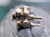
As previously posted the parts were modelled on CAD and sent for 3D printing. It tool a while for the parts to arrive. Here's what I ended up with.

The dome came out OK. There is the inevitable 'grain' from the layering of the printing process but the dome isn't too difficult a shape to rub smooth with wet dry. The tiny holes to mark the fixing screw positions can just be seen. The edge of the dome is nice and thin. It's about as thin as I think you can get away with using this process and I have to confess that I managed to chip the edge on a couple of prints when I was smoothing them down. And fortunately it sits nicely on the tapered boiler with out any fettling.

The top feed cover didn't work so well. I misjudged the thinness of the edge I could get away with on the 'top hat' cover ,and you can just see in the photo that the layering has broken the edge into a number of strands. That had to be filed off and replaced with a tiny brass shim part. The other problem, that I'd kind of anticipated but thought I'd see how things turned out, was that it's a relatively small part with some tight features and curvature and it's not very easy to clean up. I did model the fixing screw heads but they don't show up well in the photo, and anyway, they all were sanded off in trying to clean up the surface of the part.

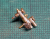
I thought I 'd have a go at fitting them to the boiler to see how they looked. I found it difficult to get a feel for them in the native whitish print material so sprayed them over grey temporarily. OK, the paint job's pants. I didn't clean up thoroughly, hence the horrid little hairy, gritty bits. Not to worry, it'll all be cleaned off before proper painting. The dome doesn't look bad. You can still see some traces of layering but I think another gentle sanding down with fine wet & dry will make them disappear under the final primer. The screw heads were made by drilling through the guide holes 0.5mm, inserting short lengths of wire and filing them back to just proud of the surface. They're appropriately subtle. You can see that the top feed cover ended up quite a mess and it'll have to come off. 3D printing isn't the way to go with parts like the top feed cover in my opinion.
So I'm still stuck for a top feed cover. There's the option to use the casting supplied with the kit but that's not great either, and in using the drawings in the Wild Swan book to produce the CAD I did confirm that it's actually too small in most dimensions. The only option left now is to scratchbuild one, and that doesn't look straightforward to me. Much head scratching before scratchbuilding.
As previously posted the parts were modelled on CAD and sent for 3D printing. It tool a while for the parts to arrive. Here's what I ended up with.
The dome came out OK. There is the inevitable 'grain' from the layering of the printing process but the dome isn't too difficult a shape to rub smooth with wet dry. The tiny holes to mark the fixing screw positions can just be seen. The edge of the dome is nice and thin. It's about as thin as I think you can get away with using this process and I have to confess that I managed to chip the edge on a couple of prints when I was smoothing them down. And fortunately it sits nicely on the tapered boiler with out any fettling.
The top feed cover didn't work so well. I misjudged the thinness of the edge I could get away with on the 'top hat' cover ,and you can just see in the photo that the layering has broken the edge into a number of strands. That had to be filed off and replaced with a tiny brass shim part. The other problem, that I'd kind of anticipated but thought I'd see how things turned out, was that it's a relatively small part with some tight features and curvature and it's not very easy to clean up. I did model the fixing screw heads but they don't show up well in the photo, and anyway, they all were sanded off in trying to clean up the surface of the part.
I thought I 'd have a go at fitting them to the boiler to see how they looked. I found it difficult to get a feel for them in the native whitish print material so sprayed them over grey temporarily. OK, the paint job's pants. I didn't clean up thoroughly, hence the horrid little hairy, gritty bits. Not to worry, it'll all be cleaned off before proper painting. The dome doesn't look bad. You can still see some traces of layering but I think another gentle sanding down with fine wet & dry will make them disappear under the final primer. The screw heads were made by drilling through the guide holes 0.5mm, inserting short lengths of wire and filing them back to just proud of the surface. They're appropriately subtle. You can see that the top feed cover ended up quite a mess and it'll have to come off. 3D printing isn't the way to go with parts like the top feed cover in my opinion.
So I'm still stuck for a top feed cover. There's the option to use the casting supplied with the kit but that's not great either, and in using the drawings in the Wild Swan book to produce the CAD I did confirm that it's actually too small in most dimensions. The only option left now is to scratchbuild one, and that doesn't look straightforward to me. Much head scratching before scratchbuilding.


.jpg")

")


 . So the cross holes are centre drilled to mark position and drilled 0.8mm only until the drill cuts full diameter. Drilling out the internal diameter using a succession of sizes 1.0, 1.5, 1.9mm increases the odds of staying on centre. At 1.9mm the drill breaks through into the grooves and the clamp rings are captured on the drill bit. 1.9mm is slightly undersized for the pipe but that gets sorted later.


