NickB
Western Thunderer
Sorry Jon,
I thought I'd answered your question but it appears not. Sheesh, anyone got a cure for failing memory? Yes, the loco is also known as a Jumbo, maybe someone can explain why. And it will be in LNWR black.
Back to the tender, and now the sidesheets for the tank. That means rivets, Hundreds and hundreds of them. Luckily Bill Finch (in his book on the Jumbos) has counted them, so we don't have to. But believe me, there are lots and lots of them. Why couldn't the LNWR use flush rivets like certain other companies I could mention?
That immediately settles the question of whether to inset or impress them. Inserted rivets can look very good, but If I went that way it's questionable whether I or the tender would be finished first.
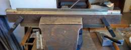
Now I have a rivet punch which I've mentioned previously in this thread but to save you searching, here it is again.

The rivet spacing can be set using anvils of different diameters. I've made a number of them and with care they can give a consistent rivet spacing, but I've found that it is diificult to get an exact spacing. It depends on the shape of the impressed rivet and how you hold the workpiece in relation to the anvil. I wanted an exact spacing to ensure that the horizontal and vertical rows of rivets lined up as they should. Yeah, I know, I'm fussy like that. For that, a template is the answer - a plate with a set of holes through which the rivets are punched.
That was made easier because most of the rivets, wherever they are on the tank, are equispaced. The only exception was some rows that were double spaced. So I decided that a template with a single row of rivet holes would do for everything.

I made sure that all corners of the plate were square and the edges straight so that it could be lined up with the workpiece for bot horizontal and verticals. CNC (or a DRO) makes it possible to drill the holes at exactly the right spacing. And off we go.

Yup, that kept me quiet for quite some time.
I know I regularly moan about Crewe, but one thing they did that makes it easier for the modeller was to overlap the sideplates rather than abut them. Why does that help? Because each corner is a separate plate and there are overlapping plates between each pair of corners fill the sides and end. Without any visible seams or joins, you have to make one plate that wraps around sides and ends and getting two (or more!) bends in the plate exactly the right distance apart for teh corners is a real pain. Been there, done that, still bear the scars.
Of course, square corners are so much easier than round ones. Why weren't they all like that?
So each plate, whether corner, side or end, is separate and can be made oversize then trimmed back to fit. The corner plates are bent around a dowel of suitable size (trial and error to allow for the spring in the material) without worrying about getting it in exactly the right place - just somewhere near.
The plates, by the way, are 0.25 mm nickel silver. That's only slightly thicker than the prototype, and that is important because you can see the thickness at the overlaps.
Four corners done.

Sides and ends added.

At least the assembly was easy!
Nick
I thought I'd answered your question but it appears not. Sheesh, anyone got a cure for failing memory? Yes, the loco is also known as a Jumbo, maybe someone can explain why. And it will be in LNWR black.
Back to the tender, and now the sidesheets for the tank. That means rivets, Hundreds and hundreds of them. Luckily Bill Finch (in his book on the Jumbos) has counted them, so we don't have to. But believe me, there are lots and lots of them. Why couldn't the LNWR use flush rivets like certain other companies I could mention?
That immediately settles the question of whether to inset or impress them. Inserted rivets can look very good, but If I went that way it's questionable whether I or the tender would be finished first.
Now I have a rivet punch which I've mentioned previously in this thread but to save you searching, here it is again.
The rivet spacing can be set using anvils of different diameters. I've made a number of them and with care they can give a consistent rivet spacing, but I've found that it is diificult to get an exact spacing. It depends on the shape of the impressed rivet and how you hold the workpiece in relation to the anvil. I wanted an exact spacing to ensure that the horizontal and vertical rows of rivets lined up as they should. Yeah, I know, I'm fussy like that. For that, a template is the answer - a plate with a set of holes through which the rivets are punched.
That was made easier because most of the rivets, wherever they are on the tank, are equispaced. The only exception was some rows that were double spaced. So I decided that a template with a single row of rivet holes would do for everything.
I made sure that all corners of the plate were square and the edges straight so that it could be lined up with the workpiece for bot horizontal and verticals. CNC (or a DRO) makes it possible to drill the holes at exactly the right spacing. And off we go.
Yup, that kept me quiet for quite some time.
I know I regularly moan about Crewe, but one thing they did that makes it easier for the modeller was to overlap the sideplates rather than abut them. Why does that help? Because each corner is a separate plate and there are overlapping plates between each pair of corners fill the sides and end. Without any visible seams or joins, you have to make one plate that wraps around sides and ends and getting two (or more!) bends in the plate exactly the right distance apart for teh corners is a real pain. Been there, done that, still bear the scars.
Of course, square corners are so much easier than round ones. Why weren't they all like that?
So each plate, whether corner, side or end, is separate and can be made oversize then trimmed back to fit. The corner plates are bent around a dowel of suitable size (trial and error to allow for the spring in the material) without worrying about getting it in exactly the right place - just somewhere near.
The plates, by the way, are 0.25 mm nickel silver. That's only slightly thicker than the prototype, and that is important because you can see the thickness at the overlaps.
Four corners done.
Sides and ends added.
At least the assembly was easy!
Nick


)")