LNWR Precedent

NickB

Western Thunderer
Now, where were we? Oh yes, tyres. Warning: this post is about turning tyres, so if you have no interest at all in lathe work, you may decide it is not for you. Feel free to move on.

And if you're one of those annoying people with a toolroom quality lathe and a zillion years' experience, this post certainly isn't for you. I'm not in your league. I'm one of those people who thought it would be fun to have a lathe and went on from there.

The first task is to reduce the blank to thickness and bore out the ID to the correct size. My chuck was only just big enough, but it did hold them securely. I used a headstock backstop so that each blank goes in the same position, and a carriage stop to avoid running into it with the boring bar. All the tyres were done using this setup before moving on.

The lesson here was the layer of hardened material that is formed by the heat of the laser at the cut edges. Reminiscent of the skin on the sand casting beloved by model engineers of a certain generation. Not tool steel hard, it does cut, but takes it out on the tool.

I was expecting that, but I was surprised how deep it was - up to 0.8mm in my case. It dulled the edge of an HSS tool very quickly. Yes, I'm still in the 20th century for lathe tools but I mostly use HSS tools because so much of the turning that I do requires a special tool form to be ground and it's a lot easier in HSS.

That was certainly true until I discovered that the awkward bits could be 3D printed.

Anyway, I switched to a carbide insert boring bar which did a much better job of cutting. The only tool I had available is much longer than I needed so it vibrates a bit and the quality of the finish is not great. But I will be gluing the centre in place, and a slightly rough finish (this isn't an argument for a ploughed field finish) means a greater surface area in contact with the glue which is all to the good.
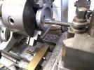
Tyre_1.png

Once the ID is correct the tyres go on this fixture. Where the tyre is mounted it is turned in situ to a good running fit on the tyre ID. Then it never leaves the chuck until the whole batch is done to ensure that the tyres are concentric.
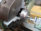
Tyre_2.png

Each tyre is clamped in position, and the first task is to reduce the OD to the diameter over the flange. Again there is a layer of hardened material to get rid of and I used a carbide insert tool for this. Incidentally, when I ordered the tyre blanks from the cutting firm, I did add enough margin on both ID and OD - just. Phew.
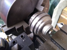
Tyre_3.png

Now to form the profile. Lock the saddle and set the top slide over at 3 deg to give the correct taper on the tyre. The tool is moved exclusively by the top and cross slides in this operation. The leading edge of the tool is set at the correct angle for the flange. Then cut to final diameter plus a very small margin (say, 0.05 mm or a couple of thou in old money).
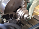
Tyre_4.png

Now for the controversial bit! I get the final shape using a form tool (from Mark Wood). I like it because the final profile is entirely consistent. Lock everything that can be locked on the lathe, use a very slow speed and feed the tool in slowly. If you do it right and keep the final cut very fine, it doesn't chatter.

People have told me they can get just as good a finish with conventional tooling and the form tool isn't worth the cost. I just checked and I see that the cost is almost double what I paid about eight years ago, so you might think twice about it. Anyway, I've done about 40 tyres in G3 so far so it's beginning to pay for itself.
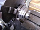
Tyre_5.png

We're still not quite finished. The surface needs some attention with a fine file (I know, sacrilege) and wet-and-dry paper. Then it is finally done.
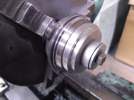
Tyre_6.png

Rinse and repeat twenty times. A pile of finished tyres is gradually building.
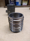
Tyre_7.png

That's it. There are lots of instructions on the web about how to turn wheels from castings, but I decided to set out how I did it from laser cut blanks, which isn't quite the same. If you stayed the course, thanks for your company.

Nick
 

NickB

Western Thunderer
Rob,

No, I didn't, but it's a good thought for next time. The hard skin wasn't the serious problem it would have been if I'd left a smaller machining allowance. Carbide toold dealt with it quite successfully.

Nick
 

Ian_T

Western Thunderer
Very nicely done Nick.

With regards form tools, I had this debate with (I think) Mike quite a few years ago. The flange depth is only 2mm for sprung axles (2.3mm for unsprung) and by the time you've cut a 10 degree angle on each side of it, a file will quickly round any sharp edges. I guess the form tool is convenient but I resisted getting one when they were £40 and it's much easier to do so now they are £78. I use a cutting tool with a 10 degree angle on one side btw, no need to change the top slide. Round nose tool for the tread at a 3 degree set-over. I rough all wheels to size and then do finishing at all the same settings.

With regards a wheel turning fixture, I have a MT2 arbor with 3" dia disk attached (think small face-plate) with a hole reamed in the arbors centre (mine is about 3/8" diameter I think). The plate has threaded holes in it as required to provide driving and/or clamping. A piece of rod is placed in the hole and held by a grubscrew. It's skimmed to the size required and threaded for the nut if needed ( or you can just clamp the casting to the faceplate btw). It will run dead true and is used as you describe. If the axle hole is the same, you can just re-use this 'as-is' next time around or turn down to a smaller size if required - so it's quite convenient. It's very simple to replace/redo the centreing pin if required though.

Just my thoughts... :)

Enjoying following this...

Regards,

IanT
 

NickB

Western Thunderer
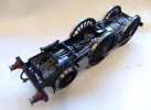
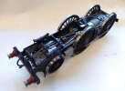
Stepping back to the engine for a moment, I've finished painting the chassis. Quite easy due to the monchrome tendencies of the LNWR. The eagle-eyed will notice that the front wheels now have the correct number of spokes.

?hash=87bf7be908314342d23c82b507b8e4a4.png

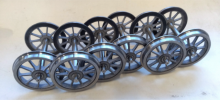
Back to the tender, I now have enough wheelsets for two six-wheel tenders. And a few spare wheels in the drawer just in case.

Tender wheelsets.png

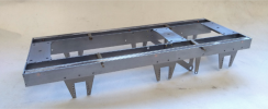
This is a trial assembly of the frames, all set up ready for soldering.

Tender frame assy.png

Nick
 

Attachments

  • Chassis painted_2.png
    Chassis painted_2.png
    594.4 KB · Views: 3

Jon Nazareth

Western Thunderer
Back to the loco. Most electrically powered locos, as far as I know, are built using a separate chassis and body, the body removing to get at the works. That's not going to work here because of the way the leading wheel spring is attached. The hangers are bolted to the frames to take the load, but the front hanger has to pierce the smokebox wrapper.

View attachment 187298

That means if you bolt the hangers to the frames, you can't get the smokebox off, but with the smokebox and boiler in place it is all but impossible to remove the spring. Incidentaly, on the real thing lead sheet was forced into the space between the hanger and the wrapper to preserve the smokebox vacuum. It all sounds like a bit of a bodge. Couldn't they come up with a better idea? Clearly, DFMA (Design for Manufacture and Assembly) hadn't been invented in Victorian times.

My answer is to attach the smokebox permanently to the frames. The boiler is part of the body assembly, and bayonets into the back of the smokebox. To remove the body, release the screws which will be under the cab, slide the body backwards about a millimetre, and lift it off vertically. It will work because there are only two external pipes connecting the boiler and the smokebox and it's easy enough to release them for dismantling.

The smokebox skeleton is a straight forward bit of sawing, filing, and turning.

View attachment 187300

Thw wrapper has two rows of rivets at front and rear. I decided to press them rather than add them separately and solder them, partly because I couldn't find any rivets of the right size, but mainly because I didn't fancy drilling so many tiny holes.

When I made my rivetting tool, many years ago, I designed it so that it could be clamped to the bed of my Sherline lathe. The work is clamped to the cross slide and moving the saddle and cross slide gives nice uniform rows of rivets in both directions. Here is the first row

View attachment 187301

and here is the second row, positioned by cranking the x-axis the correct amount and maintaining the same spacing on the cross slide.

View attachment 187302

I prefer doing it that way than relying on the anvil diameter to space the rivets. It works better for me but I know that the late, great Beeson and Reynalds both used the anvil edges, and who am I to argue?

Nick
Nick

On the smokebox skeleton, are those solid brass bars held in place with countersunk screws? Could you also tell me, please, what diameter are those bars and what thickness are the formers?

Jon
 

NickB

Western Thunderer
Jon,

The front and rear formers are 0.9mm thick (probably 20SWG in practice, it is just what I had to hand) and the spacers are 5mm diameter. The spacers are drilled through and the assembly was made with pieces of threaded rod though each one and nuts at each end. Then soldered up and the threaded rods and nuts were removed.

On the rear face of the smokebox there is a transition piece which models an extension of the smokebox beyond the wrapper. That is 1.5mm thick (scale thickness) and is held in place with three 10BA screws into holes in the smokebox rear - not the same holes as those through the spacers.

Does that make it clear? It's difficult to put in words but PM me if you wish and I'll see if I can dig out some photos or sketches.

Nick
 

Jon Nazareth

Western Thunderer
Jon,

The front and rear formers are 0.9mm thick (probably 20SWG in practice, it is just what I had to hand) and the spacers are 5mm diameter. The spacers are drilled through and the assembly was made with pieces of threaded rod though each one and nuts at each end. Then soldered up and the threaded rods and nuts were removed.

On the rear face of the smokebox there is a transition piece which models an extension of the smokebox beyond the wrapper. That is 1.5mm thick (scale thickness) and is held in place with three 10BA screws into holes in the smokebox rear - not the same holes as those through the spacers.

Does that make it clear? It's difficult to put in words but PM me if you wish and I'll see if I can dig out some photos or sketches.

Nick
Nick
Thanks for replying and that’s just the answer that I wanted.

Jon
 

Mike W

Western Thunderer
I'm still trying to figure out what Nick's next masterpiece might be. Two sets of tender wheels, so it has a tender. Spare wheels for the drawer, not for the next project, so no leading or trailing wheels. That suggests an 0-6-0 or 0-8-0. But that's as far as I get at the moment! If contemporary with the Jumbo then it could even be a Compound 0-8-0. Wow! ;)

Mike
 

john lewsey

Western Thunderer
I'm still trying to figure out what Nick's next masterpiece might be. Two sets of tender wheels, so it has a tender. Spare wheels for the drawer, not for the next project, so no leading or trailing wheels. That suggests an 0-6-0 or 0-8-0. But that's as far as I get at the moment! If contemporary with the Jumbo then it could even be a Compound 0-8-0. Wow! ;)

Mike
Quite exciting really
 

Mike W

Western Thunderer
No, I'm still no further forward. I know you have a soft spot for Lady of the Lake, but herrings are salt water fish so far as I know. Caulifowers come to mind but I don't like them with herrings either. So I think that really is a red herring and will have to be patient - damn!

Mike
 

NickB

Western Thunderer
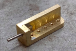
Back in the here and now, and the relative sanity of my workshop, the next job is the hornguides. I need a couple of dozen of them, so some organisation is called for, because I'd drive myself nuts if I had to mark out and cut each one individually. What we need is a jig, or several jigs. Spoiler alert! This is the end product.

Hornguides_1.png

The first question is, what are the important dimensions and features? The holes here have to align with the holes in the frame to pass the rivets through, and the hornguide must be a right angle for the axlebox to move as it should. Sounds obvious, but the answer tells us how to proceed. Get those things right and the parts will fit and do what they have to do. I can allow a bit of leeway elsewhere. Not so much as to be screaming obvious, just not to be quite so careful about.

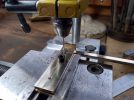
The right angle is ensured by starting with some milled (not rolled) angle of the correct dimension. The photos below shows one such clamped in a jig for drilling the holes. That way I have only to set out the holes once. The jig is also the exact width so that after drilling I can use it to cut and file the angle to length without having to measure.

The angles are LH and RH, so the jig is reversible - do one half the angles, turn it over and do the other half.

Hornguides_2.png

Hornguides_3.png

And here are the two sets.

Hornguides_4.png

One of the outer corners is radiused. I filed a quarter circle on a scrap of material of the right size, clamped it to each angle in turn and used it as a filing jig. But forgot to take a photograph - sorry.

Next up is the base which is soldered in place. Here is the soldering jig which is just a few pieces of scrap wood. It holds each angle against a strip of material that has the correct width and is much too long in order to make it easy to hold. After soldering, the base is cut and filed to size. The soldering jig has LH and RH sides, too.

Hornguides_5.png

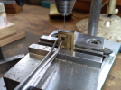
Finally, there is a hole to drill and tap in the base for the stud that will eventually hold the keeper in place. Another drilling jig is called for in which the angle can be clamped for drilling. Tapping is then done by hand.

Hornguides_6.png

Hornguides_7.png

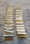
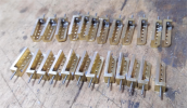
And there they all are, lined up and ready for riveting to the frame. Yes, there are two tenders' worth. It's a lot more time-effective to set up and do them all now, rather than half now and half at some later date.

Hornguides_8.png

Nick
 

NickB

Western Thunderer
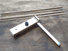
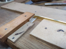
The keepers are assemblies of plates which are bolted to the hornguides and rods between them. This is the drilling jig for the plates, two holes for the hornguide studs, and one hole at one or both ends (depending on whether it is an outside or centre axle).

Keeper_1.png

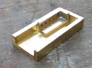
And here are all the parts for one assembly, ready for soldering.

Keeper_2.png

Once soldered, the ends of the plates had to be filed to a smooth transition to the connecting rods. There's no easy way to do this. Coarse then fine half-round needle files, followed by coarse then file wet and dry, and keep inspecting it from all angles to spot and get rid of the humps and dips.

Keeper_3.png

Nick
 

Jon Nazareth

Western Thunderer
The keepers are assemblies of plates which are bolted to the hornguides and rods between them. This is the drilling jig for the plates, two holes for the hornguide studs, and one hole at one or both ends (depending on whether it is an outside or centre axle).

View attachment 214762

And here are all the parts for one assembly, ready for soldering.

View attachment 214763

Once soldered, the ends of the plates had to be filed to a smooth transition to the connecting rods. There's no easy way to do this. Coarse then fine half-round needle files, followed by coarse then file wet and dry, and keep inspecting it from all angles to spot and get rid of the humps and dips.

View attachment 214764

Nick
 

Jon Nazareth

Western Thunderer
Another question re the smokebox, Nick. Could you tell me, please, how thick is the wrapper? I did read through your posts but I don’t think that it was mentioned.

Jon
 

NickB

Western Thunderer
0.018 in. That's about as thick as I can use. Anything thicker than that would need a special bending tool to form the lower radii.

Nick
 
Top