JimG
Western Thunderer
Now on to the Spratt & Winkle style hooks.
The plethora of recent messages may give the impression that the coupling development has been proceeding at some pace - however anything but. This recent work started in at the beginning of April and there have been one or two dead ends and also supply hold ups. I had sourced small bore brass tube in the week before the Coronation, but for some reason the tracked package arrived at the local sorting office on the Friday before the event and I didn't get it delivered until Tuesday afternoon after the holiday. So I lost a week of time waiting on getting that tubing which was needed for the hook construction. And the garden, now becoming a jungle, demands some time.
I made up a small tool to bend the hook.
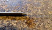
It's a bit of brass rod with a 0.5mm hole drilled 4mm deep to accept the 0.45mm brass wire. No originality here - pinched from the methods to make Alex Jackson couplings which have been around for years.
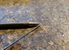
The wire is bent as far as possible in the tool - the taper helps here to allow that.
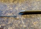
The bend is squeezed flat with corrugated jaw pliers then inserted in a 1mm hole on the other end of the tool which is 2mm deep.
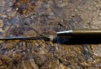
The folded end is then bent to a thirty degree angle to form the hook. This can be a bit finnicky - i.e. getting the bend square to the wire. The wire behind the hook can also get a bit bent, as shown here, but this can be straightened out quite easily with pliers.
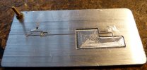
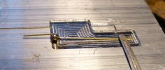
I then machined a former for the hook out of alloy strip on the CNC mill. I actually use B&Q/Screwfix strip which machines very nicely - not the cheapest source, but handy. The hook and the delay action bar channels are obvious on the left. The short right angled channel on the right is to measure out the delay arm. The sunken area allows the sidecutters to get in to cut the wire. The 8BA screw top left is the connection for the RSU return.
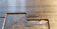
The delay bar is bent at right angles and inserted in the channel. It is trimmed to length at its left hand end and is trimmed to project 1.5mm from the channel at its right hand end, then the 1.5mm projection is bent upwards, as shown. the bends need a wee bit of squaring up with pliers when released from the jig.
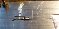
The hook and the delay bar are fitted on their channels and the hook wire is trimmed at the right hand end.
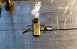
A wee bit of brass strip and a 10BA screw hold both parts firmly and a short section of 0.7mm bore tube is inserted to provide an anchor for the coupling. A small blob of solder paste is applied to the junction of the tube and the two wires then the RSU is applied to fuse the lot together.
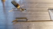
The soldered hook removed from the jig. The length of the brass tube has been filed down while in the jig.
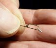
The hook and bar away from the jig. I also applied solder to the hook to prevent it being opened by pulling forces under load. the solder doesn't look too tidy in big close up - I'll hit it with the fine bit in my 45W to improve matters.
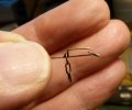
...and the three link chain fitted with the iron link at the bottom. I also prefer to bend down the end of the delay bar which gives a bit more leeway when pushing under the bar when moving into the delayed position.
Jim.
The plethora of recent messages may give the impression that the coupling development has been proceeding at some pace - however anything but.
 This recent work started in at the beginning of April and there have been one or two dead ends and also supply hold ups. I had sourced small bore brass tube in the week before the Coronation, but for some reason the tracked package arrived at the local sorting office on the Friday before the event and I didn't get it delivered until Tuesday afternoon after the holiday. So I lost a week of time waiting on getting that tubing which was needed for the hook construction. And the garden, now becoming a jungle, demands some time.
I made up a small tool to bend the hook.

It's a bit of brass rod with a 0.5mm hole drilled 4mm deep to accept the 0.45mm brass wire. No originality here - pinched from the methods to make Alex Jackson couplings which have been around for years.


The wire is bent as far as possible in the tool - the taper helps here to allow that.

The bend is squeezed flat with corrugated jaw pliers then inserted in a 1mm hole on the other end of the tool which is 2mm deep.

The folded end is then bent to a thirty degree angle to form the hook. This can be a bit finnicky - i.e. getting the bend square to the wire. The wire behind the hook can also get a bit bent, as shown here, but this can be straightened out quite easily with pliers.

I then machined a former for the hook out of alloy strip on the CNC mill. I actually use B&Q/Screwfix strip which machines very nicely - not the cheapest source, but handy.
 The hook and the delay action bar channels are obvious on the left. The short right angled channel on the right is to measure out the delay arm. The sunken area allows the sidecutters to get in to cut the wire. The 8BA screw top left is the connection for the RSU return.
The delay bar is bent at right angles and inserted in the channel. It is trimmed to length at its left hand end and is trimmed to project 1.5mm from the channel at its right hand end, then the 1.5mm projection is bent upwards, as shown. the bends need a wee bit of squaring up with pliers when released from the jig.

The hook and the delay bar are fitted on their channels and the hook wire is trimmed at the right hand end.

A wee bit of brass strip and a 10BA screw hold both parts firmly and a short section of 0.7mm bore tube is inserted to provide an anchor for the coupling. A small blob of solder paste is applied to the junction of the tube and the two wires then the RSU is applied to fuse the lot together.

The soldered hook removed from the jig. The length of the brass tube has been filed down while in the jig.

The hook and bar away from the jig. I also applied solder to the hook to prevent it being opened by pulling forces under load. the solder doesn't look too tidy in big close up - I'll hit it with the fine bit in my 45W to improve matters.


...and the three link chain fitted with the iron link at the bottom. I also prefer to bend down the end of the delay bar which gives a bit more leeway when pushing under the bar when moving into the delayed position.
Jim.

