TFW’s workshop

Mike W

Western Thunderer
A s.w.a.g. following a clue in the larger scale thread - shaft bores (stairs/lift) to connect to the tube station? The sections to represent the cast-iron shaft lining.
I agree. like these, made locally to me.
 

Attachments

  • Butlin 135427351_10164485043850507_6085262905623461639_n.jpg
    Butlin 135427351_10164485043850507_6085262905623461639_n.jpg
    134.9 KB · Views: 10

Tim Watson

Western Thunderer
A very neat Idea, and can one actually see the top of the stairs? asking for a friend.

Michael
The side of the stairwell will have a window cut into it so that the spiral stairs can be seen, Michael. These will be 3D printed by Richard Wilson, but he is currently engaged with sorting out the tube at the north end, at Caledonian Road.

The lift shaft will also have a window cut into it so that the car can be seen going up and down.

Eventually, the whole underground station at York Road will be modelled, including the cross over and tunnels: we have a full set of drawings for the tunnel construction - which will also be visible.

Copyright LT Museum.
Only the Southbound platform will be visible.

Copyright Doug Rose

Tim
 

Chris Veitch

Western Thunderer
2mm fine scale modelling, but of what?
Brilliant stuff as usual. I’m intrigued by the work holder in the tailstock - what is it?

By coincidence I also keep my Rocol and some lathe tools in an identical ice cream tub, but I suspect that’s where the similarity between workshops ends…
 

Tim Watson

Western Thunderer
Brilliant stuff as usual. I’m intrigued by the work holder in the tailstock - what is it?

By coincidence I also keep my Rocol and some lathe tools in an identical ice cream tub, but I suspect that’s where the similarity between workshops ends…
It’s an Albrecht chuck, Chris, with the brass tube supported on it’s outside. The work was only turned by hand (I now have a lathe handle on my birthday present list).

Tim
 

Tim Watson

Western Thunderer
The plate to support the shafts at YR has been fettled and aluminium plugs made to locate them. The larger mass of the central one will be adapted to locate the lift car mechanism.

The plate was chemically blacked and the tubes given a quick spray of barbecue black paint. This came out blacker than I expected and doesn’t ‘work’.

I then gave them my a spray with grey undercoat, and they can now be seen on the complete layout. They look better and are not quite as light as shown in the picture.

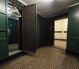
I will have to cut out the ‘windows’ for the spiral stair case and the lift shaft. I think it would look rather good with the shafts fully weathered. Question is, what would they look like? The inside looks like this:

What does the team think?

Tim
 
Last edited:

Heather Kay

Western Thunderer
I assume the "outside" of the barrels would be embedded in the local geology. It would be difficult to gauge what state or colour they’d be in. So, on that score, I’d probably paint to a similar state as the interior views. So, dusty, cobwebby, a little rusty here and there.
 

Tim Watson

Western Thunderer
It’s all a bit of a quandary, really. The iron may be in an anaerobic atmosphere within the clay so would probably not rust much. Equally it would be below the water table for some of the depth (Gasworks is a very wet tunnel). There could be water channels around the shafts.
What colour are cast iron pipes when they’re dug up?

Tim
 

Overseer

Western Thunderer
It’s all a bit of a quandary, really. The iron may be in an anaerobic atmosphere within the clay so would probably not rust much. Equally it would be below the water table for some of the depth (Gasworks is a very wet tunnel). There could be water channels around the shafts.
What colour are cast iron pipes when they’re dug up?

Tim
In clay, ugly lumpen surface with rust nodules. Mostly dark brown with bright orange to yellow rust blobs once the clay is washed off.
 

Tim Watson

Western Thunderer
Here is the lift mechanism on trial.
The timer circuit obviously will delay transit. The lift car chassis is made from steel and it is retained on the actuator by the two magnets visible on end - the ‘eyes’.

The car design is quite a complicated shape, but having it easily removable from the actuator will make life a little easier for making it. The question remains as to how much detail goes into the shaft lining as well as the guide rails for the car (which will also have a light in it).

Tim
 

Tim Watson

Western Thunderer
The lift car is taking shape. It’s built in two halves, one in steel, so as to magnetically locate on the pusher


I’m really not sure how the car would look on the outside - trawling the internet only gives so much info. The rebated corner held a guide channel / wheel? for the car with another, less conspicuous, in the far corner. There will be an omission on my model - the counterbalance weight; although I may represent the guide rails and ropes.

I am also getting a laser cut ladder-like ‘doily‘ made in thin card, which should represent the shaft lining segments - at least this will help with the weathering. It‘s all a bit crazy this game isn’t it?

Tim
 

Yorkshire Dave

Western Thunderer

Tim Watson

Western Thunderer
Top