TFW’s workshop

mickoo

Western Thunderer
If there's two lifts in the same shaft then they may not have individual counter balances, I.E. they use each other.

I used to work on lifts at BT, none of ours had wheels but U shaped slippers that ran on a T guide, at the base of the slipper was the safety brake which had it's own rope.

There was also a safety brake on the counter balance (usually), the reason for that is that the balance is the weight of the car plus half the loaded capacity. If the motor or brake was to fail, then the weight is heavier and the car shoots upward, not a pleasant experience so the brake on the weight will stop it falling and the car rising.

Having a counter balance at 150% of the empty load also reduces the size of the motor required, it's only ever going to have to move 50% of the load.

I enjoyed working on Otis lifts, their floor selector was like something out of a steam punk movie and a lot of the relays had mercury tilt switches for safety to check they were in or out, lots of clicking and clacking with corresponding blue flashes as the relays tilted.

Here's a good video of selectors and basic lift technology with some shaft views, it must have been the same man at Otis who wrote on all the relays as the handwriting was a smack in the face blast form the past for me, just how I hadn't remembered it but it all came flooding back. We had drum selectors, several with pawls on micro switches and one drum type with what we called pennies, edged discs that ran in a track up and down the selector.


The BT course was hard, four weeks and you had to get above 75% in each stage exam, fail and you went home. Fail any stage or the final exam and you were never allowed back, it was a one shot deal. I was lucky as I'd been training on lifts for several years before so passed, one of only two candidates up to that point that achieved 98%, the average was 80-85%.

Sorry for the blurb, I really liked lifts, it was the one of the few technologies I was really good at and understood well. Sadly it can be deadly, a close friend who worked for Express lifts died doing routine over travel checks at the top of the shaft, not at BT but another site they were responsible for checking and maintaining.
 
Last edited:

Tim Watson

Western Thunderer
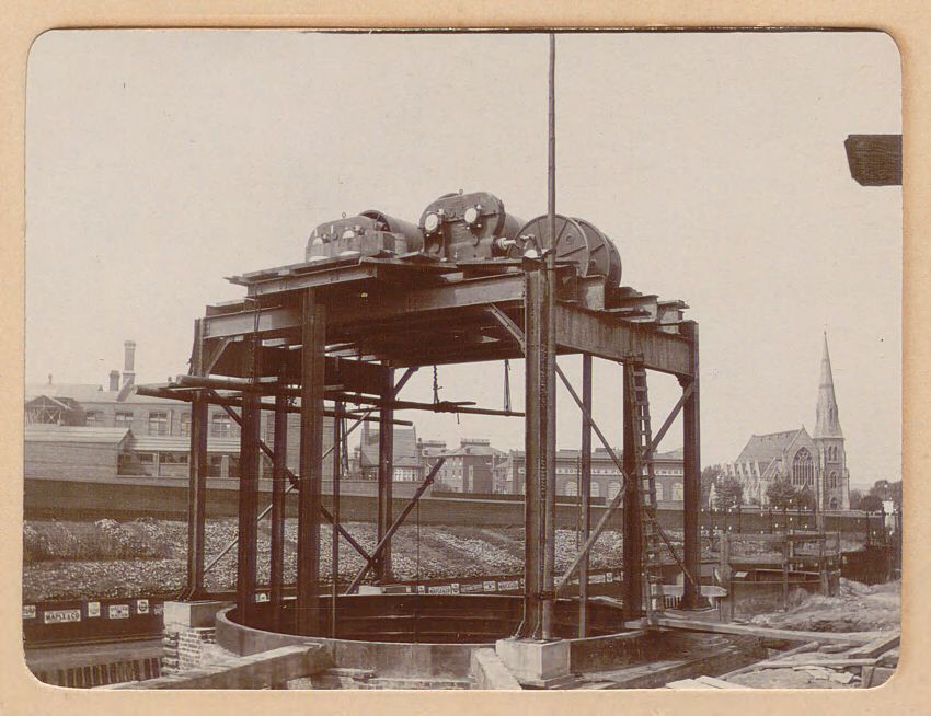
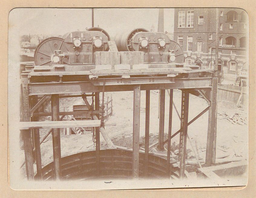
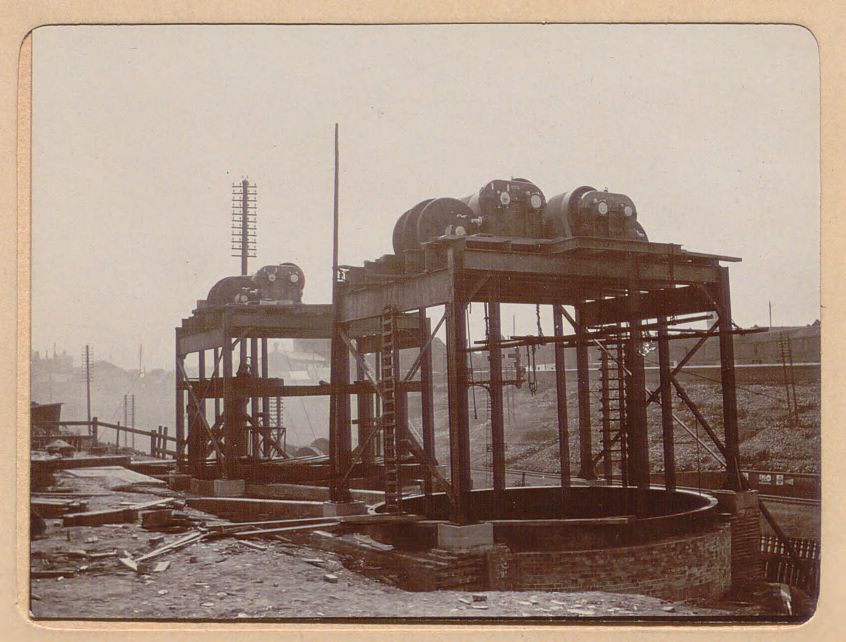
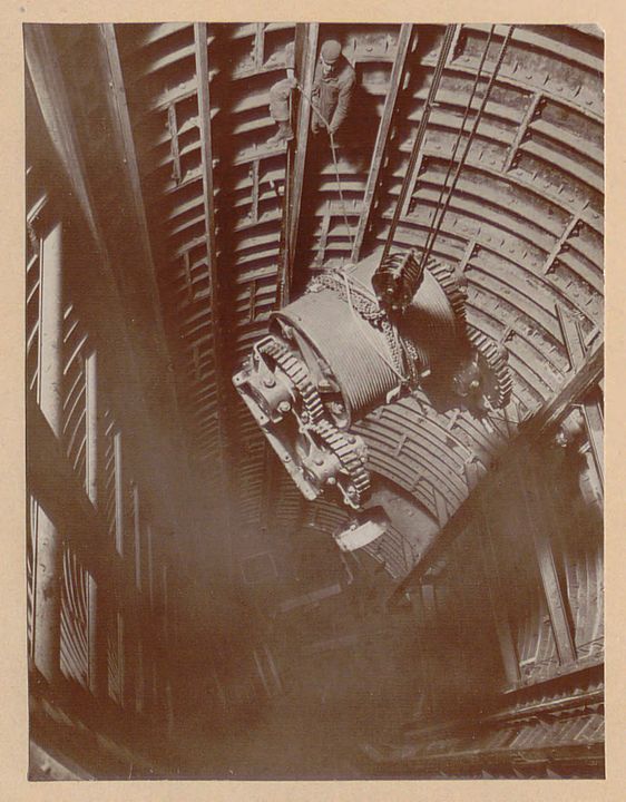
Thanks for those fascinating insights, Mick. I’m really not sure whether the cars were self balancing. The one at Aldwych is parked next to its neighbour which might imply that they aren’t. For sure the lift at YR was hand driven as the train tickets were sold by an attendant in the lift - and I doubt that there was ever enough footfall to justify any modernisation before the station closed in 1932. These photos (copyright Hagley Archive (here for educational purposes only) show the lift mechanisms being installed at Caledonian Road.


I wonder if these are drum lifts, acting as a simple hoist? Another view from Waterloo shows a winding type drum.

The trouble is, the more you know, the more you don’t.

My personal anecdote about ancient lifts relates to the old lift at the back of the Outpatients Dept at Bart’s when I was a houseman there in the early 1980s. It was driven by a one eyed Egyptian with one arm and a hook for a hand. He was very adept at closing the Bostwick gates and stopping the lift in the right place.

Tim
 

mickoo

Western Thunderer
Tim,

I hadn't thought about the interconnecting door, unless they were both mid shaft it wouldn't work and the outer door is clearly open at a landing so again, clearly not interconnected.

Operator controlled lifts required quite some skill to stop at landings with variable loads, something switch gear never really got just right, if we were within ½" of the landing that was good enough, more important was setting up the door release trigger, can't have it releasing when the lift is not level with the landing.

The period photos do show two drums and motors, again suggesting separate lifts and their respective counter balances in a common shaft.

I can't see how many ropes each lift has in those photos but there looks to be at least two diverter (outer) sheaves for the hoist ropes, both probably have two ropes on each, the centre sheave is more than likely the brake.

The two pairs of ropes go over each diverter sheave and onto the hoist drum, there will be at least three wraps for traction and prevention of slippage before heading down to the car top.

It's usual for the ropes to attached to a centre fixing point so that any stretch is even and does not cause the car to jam, in that case when the car is at the top of the shaft then the ropes wrapped around the drum will be near the centre to keep the fall as straight as possible. As the car lowers the ropes will work their way out to the edges and because more rope is laid out then the fall angle becomes less important and smaller.

The ropes on the counter balance are less important as it is narrower and they will be spaced the same as the diverter sheaves to maintain a straight fall.

In the last picture the guy has his leg hooked around a T guide, given how close the rails are each side of him I'd suggest this may be for the counter balance weight safety brake, the guide rails for the counter balance are either side

In the shadow on the right is another guy with a guy rope, he's holding onto one of the car guide rails, the cars would be orientated top and bottom in that photo like thus.

Image1.jpg

Green is the car, red the counter balance, magenta are the guide rails and blue the safety brake rail for the counter balance, the car safety brake will usually act on both guide rails and to be fair they often do on the counter balance, but in this case I see no other reason for that rail down the back of the counter balance.

Yellow is the hoist drum with three wraps of rope, the lower lift is at the top of the shaft so the ropes are in the middle of the drum to keep the fleet angle shallow or perpendicular, the upper lift is at the bottom of the shaft so the ropes are at the outer ends of the drum, the angles of the ropes between drum and diverter are grossly exaggerated.

I have no idea what they are lowering down the shaft, it does not look like a lift hoist drum, the open gears and numerous small rope reeving grooves are not indicative of a lift drum and it looks too small if it were for the cars in that shaft, compared to the pictures above it's a much smaller drum.

In the upper pictures the actual motors have not been fitted and in the top one the actual hoist drum brake can be made out. Interestingly there's a gearbox at each end and corresponding motor input shaft, therefore there will be two smaller motors per drum, probably to save space and more importantly, ensure safety and reliability as well as distributing the load evenly on that platform.

I can also make out the over speed switches on the end of the diverter sheave shafts, looks like they have four, two per car/balance weight. The over speed switch is usually a small drum with centrifugal fly weights (can't make them out in the pictures so maybe a partial installation), a single rope is wrapped around the drum and attached at either end to the balance weight and car, the attachments go directly to the safety brake.

If the main hoist ropes fail or the motor over speeds then the fly weights spin out, trip the safety brake which grabs the safety rope, that in turn snatches the rope and pulls on the brake.

I've done a live safety brake check once with a fully weighted 3 ton capacity goods lift (cast iron, not people) and the lift stopped in less than 6".

The brakes are a wedge type under the car and balance weight, the energy imparted is such that the safety rail is pretty much destroyed, distorted and the T section bowed out, that's why the rails are in sections for replacement after incident like this.

Still, all very interesting stuff.
 

Tim Watson

Western Thunderer
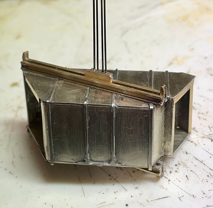
The strange-shaped lift car is now complete excepting the Bostwick gates (I have some etched fencing that will suffice until the definitive ones are produced). The steel ropes are 0.3mm pivot steel: oversize but guaranteed straight and robust.

The interior of the lift was mid green with posters above waist level. The outside? The top will be dark grey / black as it has to disappear in the lift shaft. Any suggestions?

Tim
 

Yorkshire Dave

Western Thunderer
The outside? The top will be dark grey / black as it has to disappear in the lift shaft. Any suggestions?

Top as the colour you've suggested. For the outside I'd go with the dark rusty chocolatey brown as seen on the outside of the connecting door in the photo of Aldwych in my earlier post #519.
 

Tim Watson

Western Thunderer
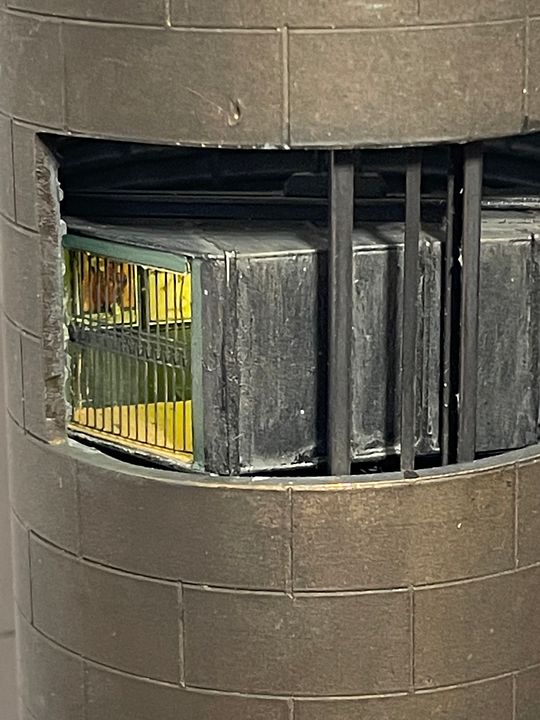
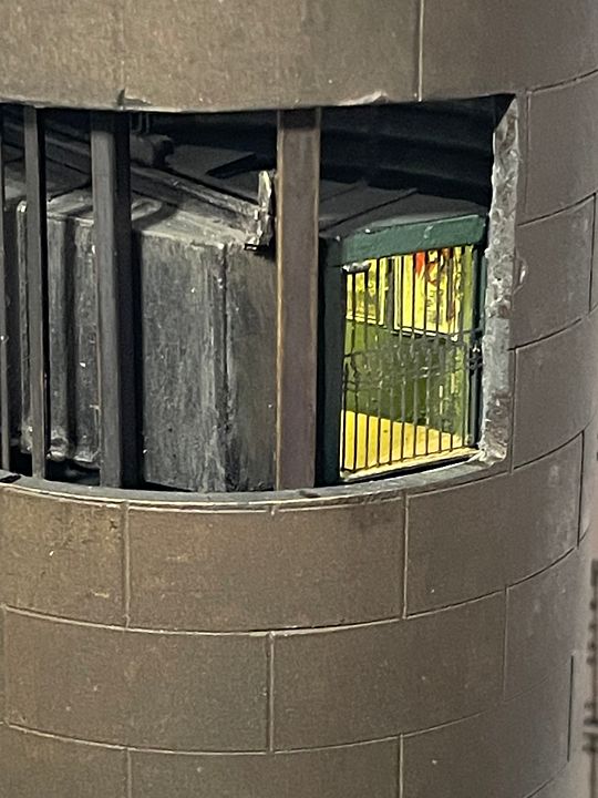
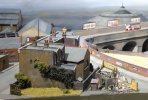
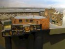
Well it’s taken far too long to make, but the working lift for York Road tube station is just about OK, pending a few final tweaks, some more weathering, the definitive Bostwick gates and correct sized posters.


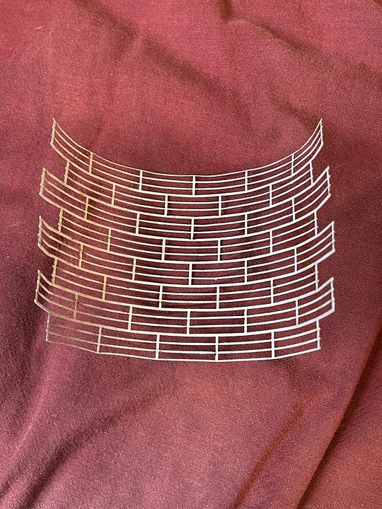
The shaft is currently just chemically blacked rather than painted. A laser cut paper lattice was used to represent the internal shaft segments.

It will be on display with the rest of CF at Ally Pally this weekend.

Tim
 

Tim Watson

Western Thunderer
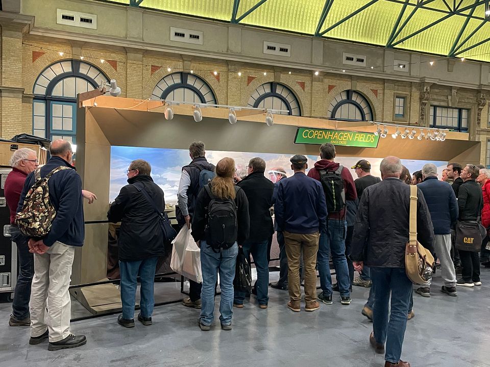
The lift worked all day at AP, was quite a popular addition. The extensive works at the south end over the last two years were reflected in the distribution of viewers being more equitable over the whole length.


At the end of the day it looked like a like this.


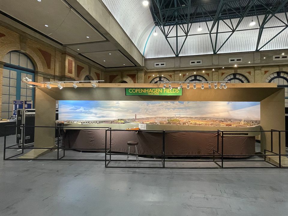
I don’t take that many photos of the whole display, but we have opened up the view at the LH end a bit, with different barrier arrangements.

Tim
 

Tim Watson

Western Thunderer
Not on the workbench yet, but I’m just warming up for a new project; does anyone know if there has ever been an etched kit for a Raven Pacific (LNER A2) in any scale?

In 4mm scale there is, of course, the DJH white metal kit. The appropriate tender has been produced in etch form and I am sourcing a 2mm scale version.

It could make a good stablemate for Valour in 1923 condition.

Tim
 

AJC

Western Thunderer
Not on the workbench yet, but I’m just warming up for a new project; does anyone know if there has ever been an etched kit for a Raven Pacific (LNER A2) in any scale?

In 4mm scale there is, of course, the DJH white metal kit. The appropriate tender has been produced in etch form and I am sourcing a 2mm scale version.

It could make a good stablemate for Valour in 1923 condition.

Tim

Apparently ACE productions did one in 0, but I can't see reference to it on their website (or at least, not the Raven version). This might be a blessing...

Adam
 

simond

Western Thunderer
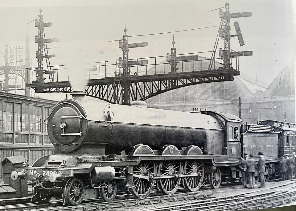
Some kind of trials going on? Any idea what the gauge might be? Steam chest pressure?

Don’t think I’d fancy hanging on to read it!
 

Tim Watson

Western Thunderer
2400 was involved in trials in and out of KX in June - July 1923: the same time that Valour was working on the Pullman trains in GC livery. A loco in NER livery will really confuse the viewers of CF.

Medley models doesn’t seem to be very active these days. I doubt there would be a market for 2mm Raven A2 etches anyway.

Tim
 

Rob Pulham

Western Thunderer
Medley models doesn’t seem to be very active these days. I doubt there would be a market for 2mm Raven A2 etches anyway.

Tim
He reinvented the brand as NER Days a few years ago and I think that he's semi retired the business but he's willing to supply 'etches only' to those who have bought from him before and won't give him any grief if something doesn't fit as it should.

When I last spoke to him (Jan 2020) he had run out of castings and wasn't planning on ordering any more.

Edited to add: In terms of potentially reducing them to 2mm, even if he was willing, I suspect it would very much depend on when he drew up the A2 etches. Much of his range was hand drawn with only the last ones being drawn on CAD.
 
Top