The Heybridge Railway, 1889 to 1913

Richard Gawler

Western Thunderer
I would like to start a topic to describe my modelling efforts for my Heybridge and Langford Light Railway. This is the Heybridge in Essex not the one in Somerset. At the moment, and probably for another year or so, this project will involve making model trains and evolving the fictional history. When I am happy with these, I will try to build a layout. I learnt the hard way, I built a layout in one of the smaller scales and then decided on the trains I could fit onto it and made a rod for my own back.

Supposing that one active topic will to be enough for me, and my "Hello" here will start to look a bit incessant or even wearying ... please, would it be best for me to set up my topic as "Area 51" (not GWR), a "workbench" (mostly workbench until the layout begins) or "Layout progress" (which will mean trains and un-seated buildings for a while).

Many thanks.
 

NHY 581

Western Thunderer
In my shoes, I would open a topic in Layout progress under a title such as 'Heybridge-An Eastern Idyll' or something equally poetic. A brief outline and then document as you go along, as you see fit. Just one topic and lump it all in as and when.

It will save managing multiple topic and you are after all 'progressing a layout'.

Rob.
 

Richard Gawler

Western Thunderer
I have discovered I can change the title of the topic. Having done this I have edited my first post to include a ToC and my posts can be reasonably well-organised. By the time I reach the end of page 3 or 4 it should be clearer whether this activity is a layout or a workbench.
The main thing to me at the moment is to post what I am making especially what I think are good ideas and particularly stupid mistakes; and hopefully see my skills improve as I go along.
I have caught up to January this year and I now have the models I built since then to mention before I will be posting in real time.
 
GER Lomac (1913 - used during dismantling the railway)

Richard Gawler

Western Thunderer
I was professionally trained how to solder ... but for electronics assembly work. I took me ages (a lot of years) to find the courage to try an etched kit. I watched a demonstation of kit building at a show, and then three modellers independently told me to try a Jim McGeown kit, "I would be perfectly able to do it". The important thing then was to totally un-learn the golden rule for electronics assembly; you really do have to put the solder on the iron and take it to the job - pretty much equivalent to writing your own P45 for electronics work.

I began with what I thought was a 45W soldering station and had trouble. The received wisdom was to use a 40W Weller with a bit like a screwdriver, but seeing the trouble I was having I bought a 60W Weller. This finished the main assembly but I spread solder all over the place underneath - the bit was 6 mm across. Two days on this iron packed up. The LEDs lit up but no heat. I took a closer look at my soldering station and saw that while the base unit was 45W (well, 45VA really) the iron attached was rated at just 20W. Well that explained a lot. I went to Screwfix and bought a 40W iron by CK. A most helpful discussion with Jim confirmed this CK iron is really a re-badged older-style Weller.

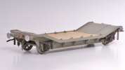
I chose the ex-GER Lomac L. The idea at the time was to pretend these were built a few years earlier than they were (to fit them into the second decade of my time frame) but realistically, the model is better used for me to represent the dismantling of the railway in 1913. I will assume the GER refused to allow the ancient dumb-buffered wagons to travel on their metals and insisted on carrying them out one by one.

P1040134.jpg

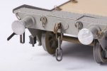
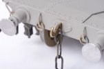
The hardest part was the lashing rails for the ends. I broke the brass wire three times before I tried round nose pliers and then I formed the rails to the wrong length. I ended up with c.15mm wire left over so full marks to Jim for providing enough material to allow for some mistakes. But really, these were horrid to make up. Hurting fingers.

P1040138.jpg

The rings themselves are soft copper wire and really easy to make (wrap wire around a small drill to make a spiral, then snip off individual rings) but soldering them up so they were "articulated" was like nailing jelly to a tree. After sleeping on this I settled on a bit of wood to jam them and hold them steady and suddenly they were easy too.

Studying this photo I think my rivets are a bit pointy and I need to back off the setting on the embossing tool (I bought the one from the Midland Railway Centre).

Looking back, my soldering wasn't all that bad. I tidied it up quite a bit with the CK iron before I put the paint on.

DSCF3291 (1).jpg

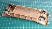
I am missing a suitable photo but the wheel bearings have to be set slightly inboard of the brass chassis. I fixed one with cyano, propped the wagon on its side, and then soldered the other bearing. Then turned the wagon over and soldered the first bearing. Gravity holds the axle and bearings nicely, the wheels spin freely but there is no unwanted end play. Then the axle box castings went on with Araldite.

DSCF3342 (1).jpg

The level of satisfaction after building this model just left me wanting to do more.

PS I have edited this a few times because I am still getting the hang of the editor.
 
Last edited:

simond

Western Thunderer
I think that looks really lovely, and I fully agree that the soldering technique is entirely different from electronics assembly!

IMO one thing that will lift your model is an improved coupling hook. It absolutely must not be brass coloured, and it wants to be a bit thicker. You might find there were enough etchings in the kit to double up, which is a good start, alternatively Premier Components do brass and steel ones. The steel ones look like steel…, but they all benefit from a bit of filing to round the edges and make the profile in plan view a bit more prototypical.

hth
Simon
 

Richard Gawler

Western Thunderer
It's funny but I thought the coupling hooks looked undernourished but they are what you get in the kit and I accepted them. Jim's kit for a tender truck (to follow) includes three pairs of etched brass hooks so you can laminate them together.

I have Jim's kit for a GWR Hydra to build next. This includes parts for two screw couplings and two three-link hooks. Supposing I remove the couplings from the Lomac and laminate the hooks together this will do one end, and use the two Hydra hooks for the other end. I know the result will be asymetric by half the thickness of the etches but the result should look better.
 

Richard Gawler

Western Thunderer
IMO one thing that will lift your model is an improved coupling hook. It absolutely must not be brass coloured, and it wants to be a bit thicker. You might find there were enough etchings in the kit to double up, which is a good start, alternatively Premier Components do brass and steel ones. The steel ones look like steel…, but they all benefit from a bit of filing to round the edges and make the profile in plan view a bit more prototypical.

Yes - sorted:

DSC_9361.jpg
Original single-thickness hook above
Replacement double-thickness hook below
DSC_9362.jpg

Some black paint will follow another day. It is a lot easier than it sounds to file these off to a "rounded hook profile".

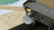
The original kit had 0.55 mm diameter piano wire to hold the buffers against the hook. This seemed a bit too sturdy. I have now used some 0.5 mm wire at one end and 0.45 wire at the other to see which gives a more realistic compression of the buffers during shunting.
 
Last edited:

simond

Western Thunderer
Looks very much better.

Rather than painting them, Birchwood Casey brass black is probably the thing.
Do read the safety advice, it’s potentially nasty stuff.

A cheap & cheerful alternative is a permanent black marker.

Ideally both: The marker after the black will be robust, not clog the links, and won’t chip.
 

Richard Gawler

Western Thunderer
I have picked up a black Sharpie and coloured in my hooks. I had dipped them in some Carr's metal black for brass beforehand, this produced the blotchy look in my photo and now they are solid black. Seems Perfect.

I wonder if I could colour in a whole wagon with felt pens, I've never been much good at painting :)
 

simond

Western Thunderer
I wish I’d done the window frames of my van with something like a sharpie. I fear a repaint…:(
 

Richard Gawler

Western Thunderer
I wish I’d done the window frames of my van with something like a sharpie. I fear a repaint…:(

I am guessing, these are the windows of your M14 van?

I have a pen filled with paint, made by Posca. They have a fair range of tip shapes and colours:
Range - Posca

I bought mine from a local craft shop. The paint will flow onto the edge of a fret as well as broader surfaces but it will need some kind of primer to stay put on brass. They seem useful for touching up minor edges and details. If the colour was a bit wrong then the effect might look like deliberate shading.
 

simond

Western Thunderer
Thanks, yes, bolections & droplights. I used my lining pen & Humbrol, and made a shambles of it, so it’ll have to be cleaned and/or repainted. If I’d only used Vallejo, it would have been so easy….

D’oh…
 
Tender truck (assumed new in 1889)

Richard Gawler

Western Thunderer
Vallejo is amazing. I have only tried two bottles so far but the results were really good. The timber deck on the Lomac is Vallejo, applied with a flat brush and it just "worked".

I would like to move on to my second brass wagon build, I have a load of photos of the build. I will try to post the first batch of these tonight, this seems sensible because I have a fresh kit to build next weekend.

DSCF3360.jpg
 
Last edited:

Richard Gawler

Western Thunderer
Tender Truck (Connoisseur Models kit)

I have 20+ photos of the build so I will post them in batches.

DSCF3378.jpg
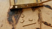
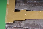
Wooden solebars have bolt heads not rivets. My rivetting tool wanted to punch holes right through (first two goes), so I backed it off, but the finished "bolt heads" are a bit small. Looking back I wonder if an automatic centre punch would have done the job better?

DSCF3385.jpg
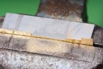
The kit seems to be designed for etched brass W irons instead of the cast white metal ones supplied, so the next task is to make spaces in the solebars for the castings. The offcut of aluminium angle helps to file a straight line as long as the file doesn’t go into it too often, and is soft enough to not mark the work. The vise is 50+ years old, it belonged to my Dad.

DSCF3389.jpg
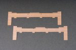
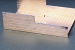
Original solebar above, modified solebar below. My filed-out rebates are a bit ragged but the wobbly edges end up hidden by the axleguards.

DSCF3408.jpg
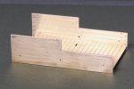
You have to make similar modifications to the outer sides. I made the rebates wider as well as deeper to make sure I would have some freedom sideways when I came to fix the axle guards.

DSCF3439.jpg
I used my CK 40W iron with a screwdriver-shaped bit about 5 mm wide, Carr’s 145 solder wire and Barrie Stevenson's liquid flux "for use with brass, nickel silver, copper and white metal" for all the soldering.

I have a watercolour brush to apply the flux, this was ok until I tried brushing flux onto the bit and melted some of the bristles.

I cleaned the bit with a brass wire brush every ten minutes of so, it seems to cake over quite easily.

DSCF3443.jpg
I held the parts togther with a miniature "Bulldog" style clip. This seemed to work fine if a bit generous with the solder.

DSCF3445.jpg
The holes for the hand rail go through after the sides are soldered together.

The clean-up was with a craft knife and 1200 grit wet and dry paper used with water, I used up my glass fibre pencil on my previous wagon.

Any thoughts or advice on the basis of this first batch of photos would be great. I have a feeling, soldering can be a bit rough and ready and will be hidden by the primer, but the neater you do it, the less clean-up you need and the quicker the progress becomes.
 

simond

Western Thunderer
A few thoughts which I hope will help.

40W might be a bit light for 0 gauge models, but much will depend on the mass of the bit.

I rather expected your cast axleguards to be soldered to the insides of the solebars. It’s probably not the best time to ask if you’re sure that filing them back was the right thing to do…

Soldering WM to brass - tin the brass with a molecule-thick layer of ordinary high-melt solder, then tin the WM with low melt, flux, and heat from a distance until the low-melt melts, remove heat and wait a moment, et voila.
 

Richard Gawler

Western Thunderer
Screenshot 2022-05-31 21.39.49.png
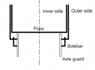
I have drawn this in Visio to try to show how the axleguards fix against the inner edges of the outer sides and the solebars. This is a cross-section across the width of the wagon. Wheels ommitted. The two inner sides and the floor are a single part folded up into a broad U shape.

The two outer sides and the two solebars fold inwards at the bottom. The rebates I have made deeper make spaces for the axleguard castings to fit against the lower parts of the outer sides and the solebars where these parts are folded inwards.

The kit instructions tell you to make these alterations and it all worked out fine in the end.
 

Rob Pulham

Western Thunderer
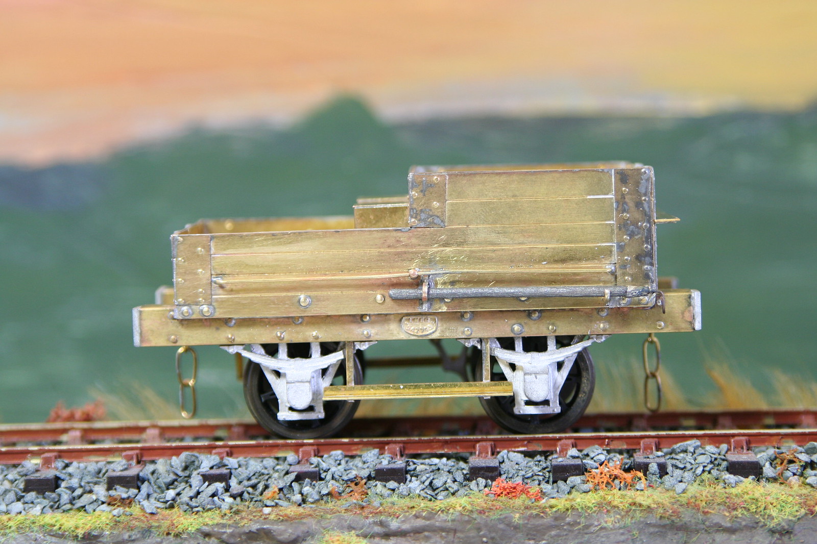
I built one of these, I don't recall needing to file need to file out the sole bars but I may have.

14393428279_db33a442e3_h.jpg
 

Richard Gawler

Western Thunderer
Rob, it looks like you drilled out the half-etched holes for the bolt heads and inserted miniature rivets. They look a lot better done this way.
 
Top