The Heybridge Railway, 1889 to 1913

Richard Gawler

Western Thunderer
After talking with you at the Show on Saturday I can see now why you were so pleased with the result of Warren's work. You have a model of which you can be proud and a model that others can enjoy when running at shows.

regards, Graham
Graham this is a good idea. I always envisaged the model as my "universal engine" to run on friends' layouts, especially their garden railways. When I saw it on Saturday I wondered if it might be a bit too good to use for this, I don't really want the lining brushing past small-leaf hedges however neatly manicured. It would be great to be able to share the model with a wider audience on exhibition layouts.
 

spikey faz

Western Thunderer
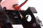
'Blackwater' threw a crankpin screw at NEEGOG last weekend. Amazingly, she ran on for another 20 feet or so before coming to a very abrupt stop. Even more amazingly, someone found the crankpin where it fell.

View attachment 187147
This isn't really an ideal design, the side rods are forever trying to loosen the crankpin screws on one side and the action swaps sides every time the model changes direction.

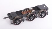
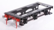
View attachment 187148
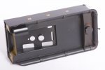
This is the underneath in case anyone is interested to see inside a Minerva Manning Wardle. The pickups are usually concealed by the wheels so I took the chance to clean them.

View attachment 187149
Everything is back together and working. The loco still runs forwards perfectly but has developed the tiniest tight spot running in reverse. I think the hard stop has put a bend in one of the two rear side rods but I cannot see anything amiss. I have eased both rods outwards a few thou', the tight spot is almost gone but it is still there. Running is perfect on a feedback controller.

The side rods are too slender to let me put in some Slater's crankpin bushes. I have secured all six screws with Loctite, I don't like doing this or even recommend it but this fault has happened before and I want to stop it happening again.
Is it possible the 'hard stop' has shifted the quartering on one of the wheels?

Oh, and Slaters do a smaller crankpin bush as supplied with their smaller diameter wheels. I converted a Minerva Hudswell Clark to Scaleseven using Slaters wheels (turned by Col) and I was able to re-use the Minerva coupling rods (which are fairly slim) with the Slaters smaller bushes.

Mike
 
Last edited:

Richard Gawler

Western Thunderer
Is it possible the 'hard stop' has shifted the quartering on one of the wheels?

Oh, and Slaters do a smaller crankpin bush as supplied with their smaller diameter wheels. I converted a Minerva Hudswell Clark to Scaleseven using Slaters wheels (turned by Col) and I was able to re-use the Minerva coupling rods (which are fairly slim) with the Slaters smaller bushes.

The model runs forwards sweetly at low speed drawing 40mA and, with the same controller setting, goes backwards at barely half the speed drawing 60mA. Something is binding and I suppose, with a rear wheel locked solid and the motor trying to turn its axle, the quartering of this wheel is the weakest link. I need to drop the wheelset and look very carefully. I will report back.
 
Last edited:

Richard Gawler

Western Thunderer
Yes, there was a quartering problem and I have fixed it.

The Minerva wheels are a force fit onto 3mm axles. Scrutinising the three wheelsets, the leading and centre wheels had matching 'quartering', while the trailing wheels (which have the axle carrying the gear) were 'different'. A bit worryingly, I can twist theses wheels relative to each other with my fingers and without resorting to the rubber gloves. I now have a model which runs at the same speed in both directions for a given throttle setting. The motor is drawing 42 mA forwards and 50 mA reverse but I cannot see or hear any difference in performance between the two directions.

So I think this is fixed for now. I have a lathe and one day I could bore out the axle bushes to 1/8 inch and install some Slater's wheels. I am inclined to leave doing this until slippage of the factory wheels becomes unbearable.
 

simond

Western Thunderer
Richard,

Whilst boring the bushes might be easy, how will you fit & fix the drive gear to the thicker axle?

if the whole axle, wheels and gears assy can be removed from the loco, would it be practical to pin the wheels (and drive gear maybe) to the axle? If you can hold (in a fixture, not by hand!) it at a suitable angle, you can probably drill the hub & axle with an 1.0mm solid carbide drill like these, and just push in a wire pin, with a drop of cyano if required.


Very fast, gentle feed, very rigid fixture!

atb
Simon
 

Richard Gawler

Western Thunderer
Simon I like your idea but not for this model. The wheels are metal and the insulation is at the hub. This probably explains why it is so easy to turn the wheels on their axle. I guess the gear for a 1/8 inch axle would be a custom job.
 

Richard Gawler

Western Thunderer
A year on WT!

Thank you to everyone for your kindness and support during my first year here. This is a fine place and I am thoroughly enjoying myself both here and in 7mm scale. A special thank you to the members of the Flying Squad who are obliged to read every new post and therefore had to plough through my back-story and other ramblings.

Trying to post something suitable for everyone, here is an illustration from a children’s reference book I bought to help my project.

dk.jpg
From “Eyewitness Victorians”, abridged edition published in 2021 by DK / Penguin Random House.

There is no mention of a water tank, though a caption above the tender explains, "coal was stored in this truck". Which is true. I bought my copy remaindered in Chelmsford Market, the idea was to get a simple introduction to Victorian life :)
 
Last edited:

spikey faz

Western Thunderer
Simon I like your idea but not for this model. The wheels are metal and the insulation is at the hub. This probably explains why it is so easy to turn the wheels on their axle. I guess the gear for a 1/8 inch axle would be a custom job.
There's a few articles in the Scaleseven Society on converting Ixion/Minerva locos to accept Slaters wheels.

When I converted my Hudswell Clark I reamed out the axle bushes and gear wheel to accept the larger Slaters axles. To help the gear stay put on the axle the article said to centre punch the axle several times where the gear sits. The centre punching actually raises the surrounding metal a bit and provides a bit more grip for the gear. It's all covered in the articles and I've not had any issues since with gear slippage.

Mike
 
Last edited:

chigley

Western Thunderer
A year on WT!

Thank you to everyone for your kindness and support during my first year here. This is a fine place and I am thoroughly enjoying myself both here and in 7mm scale. A special thank you to the members of the Flying Squad who are obliged to read every new post and therefore had to plough through my back-story and other ramblings.

Trying to post something suitable for everyone, here is an illustration from a children’s reference book I bought to help my project.

View attachment 187367
From “Eyewitness Victorians”, abridged edition published in 2021 by DK / Penguin Random House.

There is no mention of a water tank, though a caption above the tender explains, "coal was stored in this truck". Which is true. I bought my copy remaindered in Chelmsford Market, the idea was to get a simple introduction to Victorian life :)
thank you for your input Richard

Ken
 

Richard Gawler

Western Thunderer
There's a few articles in the Scaleseven Society on converting Ixion/Minerva locos to accept Slaters wheels.

When I converted my Hudswell Clark I reamed out the axle bushes and gear wheel to accept the larger Slaters axles. To help the gear stay put on the axle the article said to centre punch the axle several times where the gear sits. The centre punching actually raises the surrounding metal a bit and provides a bit more grip for the gear. It's all covered in the articles and I've not had any issues since with gear slippage.

Mike

DSC_3042.jpeg
I do like the idea of using centre punch marks to raise the surface of an axle. I did this on Nellie my crane tank to add some resistance to the rotation of the crane jib. It was a partial success, using multiple marks instead of one would be better. I never imagined I could use it to make something an interference fit.

I added the screw to resolve the jib's tendency to swing out of gauge, I can remove this to pose the jib for photos.
 

PhilH

Western Thunderer
The late George Mellor of GEM showed me this method of fixing a gear on an axle after I'd bought a gear set from him and took it back complaining that it wasn't a tight fit on the axle.

Sketch.jpg
Mount the axle (coloured yellow) vertically in a vice and clamp against it a flat file (coloured blue). Flat files usually have one edge with teeth and one edge smooth, so fix the edge with the teeth against the axle and the smooth edge against the vice jaws. Then tap the file gently with a hammer so that it turns the axle and makes a series of knurls round the circumference of the axle, the amount of pressure applied by the vice jaws determines the depth of the knurls. If the gear wheel is still not tight enough repeat the process with more pressure from the vice.
 
Top