Allen M
Western Thunderer
That is how Rovex/Triang fitted the gears to thousands of their original locos. May still do for all I know.makes a series of knurls round the circumference of the axle, t
Regards
Allen
That is how Rovex/Triang fitted the gears to thousands of their original locos. May still do for all I know.makes a series of knurls round the circumference of the axle, t
That all looks very neat Richard.View attachment 187458
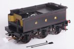
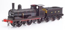
To recap slightly, this is my Y14 and its tender on 15th March this year. I bolted the subassemblies together before sending them off to Warren for painting.
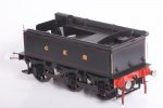
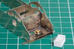
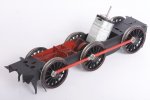
I have now completed the subassemblies for the tender, so here are some photos of this activity.
View attachment 187449
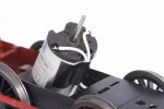
The r/c speed controller has no output protection. A dead short across the motor terminals is Unlikely but if I fit a fuse and it never blows I will have some peace of mind.
View attachment 187450
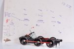
As an apprentice in the 1980s, machine screws were not only still used, but were tightened so the slots matched up.
View attachment 187452
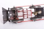
I like this palette of black and bright metal with red highlights and it is going to continue thoughout the model.
View attachment 187454
Warren asked me to leave the axleboxes and springs off the footplate assembly to make his lining task easier. I have now put them, I used epoxy glue straight on top of the paint.
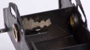
I found some daylight between side frame and fooplate. I suppose, I never looked for it properly. It's a bit late to get the torch out so I put a narrow bead of the epoxy along the inside of the gap. I used masking tape to keep this tidy.
View attachment 187456
I warmed the glue with the hair dryer and this is where the glue crept through to the outside. It won't show from usual viewing angles.
View attachment 187451
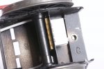
The bosses on the backs of the axleboxes fouled the hubs of the wheels so I filed them down to suit.
View attachment 187455
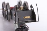
There isn't enough room for 10BA nuts on the buffer stems but there is room for some small bore tube with a flat filed onto one side. The stems are steel and the tube is brass, so I simply let the buffers cut their own threads and screwed them into place.
View attachment 187457
This is the completed footplate assembly. The lining on the buffer beam and buffer stocks is almost unbelievable. I have left off the coal regulator, this can go back at the very end after the wiring is done
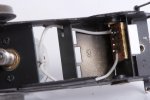
I put a lot of planning into this build. Time will tell whether I did enough, but the shortened flange on the fooplate between the leading and centre axles makes a space to let me reach the programming button on the speed controller board.
View attachment 187453
The rear handrails go into small-bore tubes soldered into the body, so it was easy to fix these into place (nail varnish) and hopefully they will stay put.
View attachment 187459
The prototypes had a visible line between the flares and the tank sides but I found it difficult to provide something right. This looks a bit rough here but it will look better when the model is moving on a layout
View attachment 187460
I found the equivalent joints on the top much easier, lots of 100 degree solder filed to shape.
This completes the work on the tender before adding the r/c equipment.

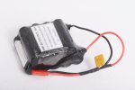
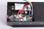
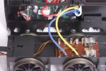
The charger was supplied with the kit of r/c equipment and appears in my very first photo of the project. The loco has two 'modes of operation' being 'charge' and 'run', these selected by a toggle switch beside a charging socket in the coal space.What recharging arrangements have you adopted, Richard?







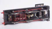
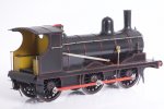
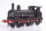
GER Y14 Project for Winter 2022-2023
Back in the summer I bought myself a Connoisseur Models kit for a LNER J15; and building this up as a GER Y14 is going to be my project for the winter.
My imaginary Heybridge Railway is a short branch off the former Witham to Maldon branch and some members of the class worked the line in BR days. Going back to the 1890s, I don’t have any photographic evidence but I would like to think the Great Eastern Railway operated the locomotives on the line back then. The Y14 had a very good route availability (RA 1) so it could work across the timber viaducts near Wickham Bishops.
I doubt I will ever have room for a home layout large enough to let an 0 gauge locomotive run at any speed or over much distance but I do have access to the club test track, two and possibly three garden railways, and the layouts at another club. These are all sociable places and, well, I want to have a mid-size loco of my own to take along to haul my wagons and my friend’s trains. These friends and others have variously opted for two-rail, three-rail, stud contact, analogue and digital command control (!) . . . .and so a dead-track loco using battery power and radio control seems like a good idea for me. I can take along my loco and its own controller and it should be able to run on any 0-F or 0-MF trackwork. "Only clockwork could be easier".
(As an aside, this also means for my Heybridge Railway there is a separate controller for through workings by the GER).
View attachment 171905
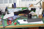
I have cleared my bench and this photo is my version of an unboxing video for WT.
This lot ought to keep me out of mischief for a while?

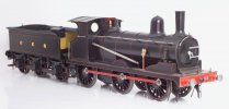



The credit roll is a nice touch... thinking about the credits for Marvel films the last part of the film is a scene that gives an insight into the next movie. As this model can be described, at least by me, as "Marvel-ous" then surely you can finish off this instantiation by hinting at the next tale from Heybridge.
regards, Graham
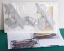
Coming next - a ballast wagon from Gloucester.

