The Heybridge Railway, 1889 to 1913

mswjr

Western Thunderer
I looked online myself as i first thought that they were too close to the driver and would be a lot different, so i was amazed to see them as you have them, There are others as well, especially earlier locomotives, so top job. a nice build.
 

Richard Gawler

Western Thunderer
23. Reverser Reach Rod

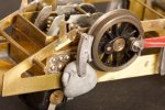
The forward part of the reverser reach rod is clear to see in photographs of prototypes and I have tried to replicate this on my the model.

DSC_5203.jpeg
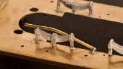
The kit does not seem to provide any support for the reach rod so I have used a piece of wire at the front, and the back of the spring further up. The wire will end up behind a sand box so it will only show if I really look for it.

I have my doubts about the curve but if the rod is straight it will end up near the handle of the reverser lever. By bending it downwards, it fits underneath the locking quadrant.

Edit: The locking quadrant is about 2 mm below its "scale" location (I simply lined it up with the mounting holes on the firebox wrapper) so I can try relocating this another day. The reach rod will still need a vertical curve, but not as much.
 
Last edited:

Richard Gawler

Western Thunderer
I truly thought, the reverser reach rod was worth a subheading and I could deal with it with one post. But no . . .

DSC_5330.jpeg
I have removed the locking quadrant, filled its locating holes in the firebox wrapper, and put it back about 2 mm higher up. I straightened up the reach rod and shortened it to finish in line with the operating lever.

DSC_5334.jpeg
I have given the reach rod a horizontal offset so it reaches up to the lever. This is starting to look more business-like.

During the course of this rework I decided to solder up the pivot for the lever. I think it is best for it to sit in forward gear than to be posable for a few photos and then repeatedly sit itself in the wrong place. The home-made lever (which I based on the kit part) is unchanged but somehow this looks better too.

I have filled the unwanted locating holes in the firebox wrapper with wire and solder. One day, after the model is finished and painted, I can look at it and remember the smokebox door. It went on first time, and without modification or substitution.
 
Last edited:

Richard Gawler

Western Thunderer
The instructions do not explain how to fit the reach rod. Somehow, the very last clause seems a bit telling: "Do not forget the reverser reach rod after uniting the body and chassis". The reach rod gets a mention in the parts list too, but this is all. How glad I am to have done it now.
 
Last edited:
( Diversion: 925 and Charlie visit the Middy )

Richard Gawler

Western Thunderer
Nellie visits the Middy.

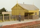
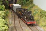
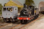
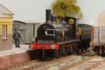
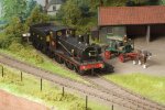
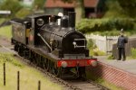
The history of the Heybridge Railway records that Nellie the crane tank was destroyed during the Zepellin raid of the night of 15/16 April 1916. The "might have been" scenario here depicts the arrival of Nellie at Debenham (this was, of course, on the extension of the Middy) and captures the reaction of a passenger waiting at the time.

View attachment 184498

View attachment 184499

View attachment 184500

View attachment 184502

Photos by Tony @Osgood

925 and Charlie visit the Middy

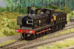
I have done a bit more "cuckoo modelling" if this is the proper term, this is to say putting my models onto someone else's layouts to take photographs. The Middy opened its line from Haughley to Laxfield in 1904. I have modelled 925 in its pre-1900 condition, so please excuse the mild anachronism here; the location is just right for a Y14.

DSC_5319.jpeg
'Debenham' is an 0 gauge layout built by Paul Clarke and now with a new owner. Nellie came here last April.

DSC_5281.jpeg
The down freight has stopped just short of the station with a derailed tank wagon. I guess the prospective passenger still has a long wait.

DSC_5275.jpeg
The loco has been turned elsewhere and returned along the branch.

DSC_5260.jpeg
The wagon on the right here is the work of @Rob Pulham.

DSC_5214.jpeg
'Cratfield' is a 7mm scale layout built by the late John Watson and thankfully preserved.

DSC_5229.jpeg
An unusual light engine movement photographed on a Sunday. A villager has reported the repeated discharge of a shotgun in nearby Grouse Field, and the Constable has had a quiet word with the crew.

DSC_5244.jpeg
Again, the locomotive has turned off-scene, this time before coaling.

DSC_5304.jpeg
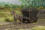
Finally Charlie and his chauldron wagon. Charlie can't tell the difference between 0 gauge and S7, but please do not look too closely at his harness.
 
Last edited:

Richard Gawler

Western Thunderer
24. Motor Mount

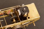
Part way through adding the brake gear I realised the chassis mechanism was binding. I took a few hours to sort this out - eventually I realised the problem was in a wooden wedge I had placed between motor and chassis to stop the motor rocking to and fro. The wedge was constraining the motor so much, the rear axle (or perhaps the gearbox final drive) was binding on each revolution of the driving wheels.

DSC_5350.jpeg
So, the wedge has come out and a blob of Blu Tack has gone in.

This has produced a vast improvement - indeed, the chassis now runs as well as it did before I secured the motor at all.

There is more detail of this on Simon D's workbench thread.
 

Richard Gawler

Western Thunderer
25. Brake Gear

The instructions omit any explanation of how to assemble the brake gear, so I present one here. I assembled the right side first, and found it thoroughly fraught and difficult. Taking some photographs of the procedure next time seemed calming so here is the build of the left side.

The parts involved are:
  • the cast brake shoes and some wire to represent the pivots
  • 12 actuating lever
  • 13 pull rod
  • 11 actuating rod
  • 10 brake crank
written out here in sequence of initial placement :)

DSC_5351.jpeg
With a rigid rear axle (hard tail?) the brake blocks go close to the wheels without fear of shorting.

For the front brakes (where the wheels have suspension), I tried and failed with smears of Araldite and settled on gluing strips of thin card onto the brake blocks. I touched these with sanding sealer before trimming to final size. They are nearly impossible to see, so no photo.
DSC_5341.jpeg
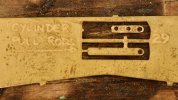
I had managed to lose the second actuating lever so I made a new one. Once again I am thankful to @Martin Shaw who let me have his stash of old frets. Thanks Martin, it has made me all kinds of detail parts.
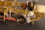
DSC_5352.jpeg
The actuating lever has received one pivot pin, and some Blu Tack stops it falling out.
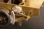
DSC_5354.jpeg
The actuating rod has received both of its pins, and is again placed loosely. The actuating rod has to go on now, because it ends up underneath the next part. "Do not remove the Blu Tack yet". Truly. If you do, start again . . .

DSC_5359.jpeg
The pull rod has received both of its pivot pins, and is soldered into place at both ends. Doing this sets the angle of the actuating lever, so this can be fixed into place too.
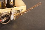
DSC_5360.jpeg
The crank (above the hair pin) is trimmed, and added to the assembly. The crank is resting on the heavy transverse rod (*). This sets up the final angle of the actuating rod, so the crank and actuating rod are soldered together. There is a loose washer waiting behind the crank.

DSC_5364.jpeg
The actuating rod is soldered onto the actuating lever. A second washer has been placed onto the heavy transverse rod.


The two loose washers are brought together and soldered up to create a boss for the crank.

(*) Please excuse me if I am using the wrong terminology. I am taking it from the instructions where I can, but I had to make this up.

And there it is. I have finally realised, the kit instructions are almost certainly the work of two people. Firstly (I suspect), someone who designed and built the kit, who prepared the illustrations; and then someone who had never built the kit and added a narrative. This would explain why the illustrations are genuinely useful; and the narrative is virtually free of useful information. I accept, the instructions are of their time, as is the kit; I expect will try something more recent next time. Or, as a kindly member of NEEGOG suggested yesterday, scratchbuild. At least I would know where all the parts were meant to go.
 
Last edited:

Richard Gawler

Western Thunderer
I reckon (again :) ) it’s a push rod.

An image search for 'push rod' returns results for rods with a dome at one end, which does the pushing.

Part number 13 has fixings for pivots at both ends. I agree, it is functionally a push rod when the brakes are applied; but it operates as a pull rod when the brakes are released. If we give it a name based on what it looks like rather than what it does part of the time, then pull rod is fair.

The instructions call it a pull rod. If I give it a fresh name I risk adding confusion or appearing overcritical of the instructions; and probably both. Then again, I want to call it a push rod too. We could talk about the brake "hangers" next, because they hang upwards so to speak :)
 

Richard Gawler

Western Thunderer
Hi Richard
A bit more info with photos. First I don't have one of the other side.
There is no motor/GB as it was built to be a static exhibit in the Colonel Stephens Museum Tenterden K&ESR. From memory the motor/GB you have should fit OK but as I built it in 2009 without not 100% sure. If my memory is correct the the rear axle is fixed with the motor and the front axle rocks with a center bearing. View attachment 195106View attachment 195107

Allen used small-bore tube to represent the heavy transverse rod. This is much better than my method, because the brake cranks (part 10) and the brake actuating lever (part 9) will fit over a length of wire placed inside the tube. So you get a scale-diameter rod and unmodified parts fitting together.

DSC_4304.jpeg
I couldn't easily take a step backwards and use Allen's method because I had already modified the actuating lever (from my post on 12 September).

DSC_5383.jpeg
Here is the completed brake gear on this side of the model. The red mark is reminding me, this is the corner where I opened out the end of the side rod and I shouldn't do it again.
 

Richard Gawler

Western Thunderer
26. Test Running (1): 9V Battery; and Control Decisions

I took the loco to NEEGOG last Saturday (11th November), where it ran for well over 30 minutes.

WhatsApp Image 2023-11-11 at 18.44.02 (1).jpeg
Thank you to everyone who told me how well the model runs. It never derailed, never faltered and merely started to slow down as the battery gave up. The chassis rather exceeded my expectations - I start to see nuances as faults when running with an umilical on a short track. The mechanism is smooth and quiet.

P1050553.jpeg
When the PP3 battery was past its prime and I had lightened the load, the loco managed a scale 10 mph or so. I am waiting for the r/c parts to arrive in the post - then I can do some tests, find out whether the loco will get r/c or conventional pickups.

DSC_5387.jpeg
So, this is a good time to have a short break from the construction. These are my completed assemblies and detail parts which will need painting, plus the base of the tank. I am slightly amazed, the sand pipes pass behind the brake rods. I had forgotten all about the pipes.
 
Last edited:

Richard Gawler

Western Thunderer
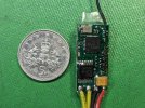
The Micron radio equipment arrived last week - a controller (the throttle) and a receiver.

WhatsApp Image 2023-11-13 at 17.41.30.jpeg
This is their MR601a receiver, brand new to market. This a 2.4GHz radio receiver and a 1.2 amp motor speed controller. I think this is incredible, and it can sit inside the lower half of the boiler too.

I need to make a few decisions before I take the build any further . . .
  1. I want to keep a 12 volt motor because this will let me run the model using a conventional analogue controller if the r/c doesn't work out as well as I hope.
  2. Test runs have showed me, the loco manages a scale 17 mph with a fresh 9V battery, and 9 mph with stale 7V one. This is with a 45:1 gearbox and the loco carrying its PP3 battery. The receiver is happy with either supply voltage, so I can see a choice of either staying with a 9 volt battery or swapping the gearbox for a 36:1 one and trying two 3.7V batteries.
  3. If 9V batteries run down too quickly, the 36:1 gearbox might help.
  4. The receiver draws a steady 28mA regardless of whether the motor is running or not, and the motor draws about 150mA with the chassis liffted off the track. I will make a guess, the motor takes 220 mA maximum on the track and hauling a train. This makes 250mA in all.
  5. Historically I have always thought of the PP3 battery as being around 150 mAh capacity - not enough. But we can now buy a Lithium Polymer battery in a PP3 form factor, an integral charging circuit and a promise of 1,000mAh. The battery has a USB-C port for charging and the only significant constraint is a maximum steady load of 300mA.
  6. Suppose the loco has a duty cycle of 1:5 running to idling on a shunting layout, then its average current consumption will be
    30 + ( 220 / 5 ) = 75 mA, so the endurance from the LiPo battery will be 1,000 / 75 = 13 hours. Alternatively, if the model is on a roundy-roundy I might get 1,000 / 250 = 4 hours. Both figures are ample.
The motor makes more torque at higher revs, which swings the choice in favour of the higher voltage; and a PP3 battery will almost fill the inside of the saddle tank, so it uses the space very efficiently. But the LiPo battery, if it really delivers what its spec says, is a real game changer. So I will try the install with a PP3 battery. I am expecting two of these to arrive this week, one for the controller and one for the loco.
 
Last edited:

simond

Western Thunderer
I’ll be interested to see how the LiPo PP3s work out. I suggest you check carefully that they are CE marked and from a reputable supplier.

The dangers of lithium batteries seem to lie in charging them, if the BMS is dodgy, or the cells themselves of course.
 
Top