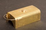
The Heybridge Railway, 1889 to 1913

simond

Western Thunderer
I’m a little uncomfortable with the idea of soldering to the battery terminals, even NiMH ones. I guess if you’re quick…
 

Richard Gawler

Western Thunderer
I think it is easy to get carried away with fears which turn out to be unfounded. Years ago I put a crossbow bolt through a phone battery (bolt launched at about one metre distance) to see what happened, and the result was absolutely nothing. Just a neat and clean installation of bolt into battery. I gave it my boss to remember our mutual frustration with the standards at the time, I took it to him in Edinburgh by train because I thought the security people at Stansted might kick up a fuss.

I bought my PP3 batteries as a pair. I could try to destroy one to see what happens. I have one those gas-powered weed killer lances, maybe put one of the batteries on the patio and have a play. But the battery weighs about 22 grams, so if we allow 10 grams for the terminals, circuit board, electrodes and housing there is only 12 grams of electrolyte. I am in Essex and even if I can get some action, it won't be visible in Kent.

The housing is in two parts, a sealed part with the electrolyte and an open part with the USB port. I'll be working at the USB port end.

So I suggest, relax. Perhaps with a suitable book:
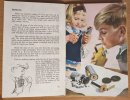
WhatsApp Image 2023-11-26 at 17.15.54.jpeg
This is in one of my favourite books from when I was a kid: "Magnets, Bulbs and Batteries", a Ladybird book.

I didn't feel much of a tingle so I tried putting the carbon rod into my mouth, complete with its coating of electrolyte, to see if my saliva would make some electricity. I ran to the bathroom and washed out my mouth for ages, I thought I was going to die.
 

simond

Western Thunderer
Many moons ago, I was unwell, so after work, Dad set up the Hornby Dublo on the bedroom floor. We had a decent collection, second hand even then. It had a “working mail coach” with a fourth rail. Dad drove the trains. I was leaning out of bed, to which I had been ordered by my mum who was a very conscientious mother, with the mail coach button on the end of a length of two core bell wire. I put it in my mouth.

You can taste 15VAC…


I’m almost sure it’ll be ok, but I wouldn’t let my staff do it…
 

Richard Gawler

Western Thunderer
I’m almost sure it’ll be ok, but I wouldn’t let my staff do it…

Furthermore, you wouldn't ask your staff to do it. There are going to be differences between hobby activities and manufacturing industry because hobby work is often a one-off and experimental; and the hobbyist is choosing to do the task. I have soldered wires onto alkaline PP3 batteries without trouble, my fear is always the heat from the iron dislodging an unknown connection on the inside but so far this hasn't happened.
 

Richard Gawler

Western Thunderer
I’m a little uncomfortable with the idea of soldering to the battery terminals, even NiMH ones. I guess if you’re quick…

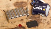
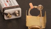
To be honest, I don't really want to solder to the battery terminals. It is a bit quick and dirty and it makes battery renewal longwinded. So I am trying a more conventional approach. There isn't room for a full-size battery snap so I have improvised . . .

DSC_5492.jpeg
I have include the spot of blood to show the real dangers of stripping down a metal-clad battery - the torn edges of the can are like a razor. I was expecting to find six AAAA (quad A) cells in here not a pile.

DSC_5496.jpeg
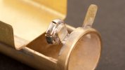
Home-made solder tag tapped 12 BA, screw soldered solid behind.

DSC_5502.jpeg
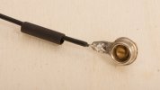
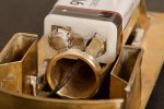
A "positive ground" chassis like my Mum's Morris 1300. Simply because the negative terminal is smaller and a little easier to protect with insulation.

DSC_5501.jpeg
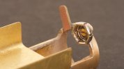
The scrap of PCB material stops the negative terminal touching the chassis. 10BA screw for the positive terminal because it has a larger hole.

DSC_5498.jpeg
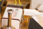
The LiPo battery and the business end of its receptacle.

DSC_5506.jpeg
Completed assembly. There is enough end play to let me put the battery in and lift it out.
 
Last edited:

Richard Gawler

Western Thunderer
I am rather making things up as I go along. Putting one battery connector on a flying lead and the other on the chassis means if I try to put the battery into the model the wrong way round I cannot put a reverse polarity onto the r/c receiver. Putting the negative terminal on a flying lead makes it easier to insulate. The rigid snap connector for the grounded chassis removes any trace of movement in the battery. So far so good.

DSC_5507.jpeg
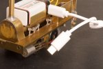
I am now toying with cutting a narrow vertical slot in the saddle tank, in line with the charging connector, to let me plug in the charger without lifting off the tank. I know this sounds like putting a hole in a clockwork model to insert the key but innards of the charging socket are black and if the loco is black then the slot would hardly show. The idea has come about because I noticed the USB-C plug is long enough to clear the thickness of the wall of the saddle tank.

Tied in with this, I have just realised that when the charging cable is attached, the outer housing of the USB-C cable plug gets connected (inside the battery) to the battery negative terminal. The body of the charging plug would thus end up rather close to the positive ground of the bodywork.

DSC_5510.jpeg
There is also a more insidious problem if one of these birfucated USB charging cables gets plugged into the model, with the free end near unpainted metalwork like the slide bars.

Obviously I could rebuild the battery snap connectors to arrange a negative ground, turn the battery over and put the slot on the other side of the model, but somehow I don't really want to do this. Mainly because when manipulating the saddle tank it would be quite easy to touch the positive terminal with the edge of the tank and put a short across the battery terminals through the (now negative) chassis.

Fundamentally, I have designed the saddle tank to lift off for charging and the battery terminals to minimise the likelihood of a short circuit. If I go for the slot, the paintwork would discourage an easy short circuit if someone puts a metal object into the gap between charging plug and bodywork. The best mitigation against the bifurcated cable (supplied with the two LiPo batteries) is to throw it away.

I wonder which approach might be better.
 

magmouse

Active Member
I know this sounds like putting a hole in a clockwork model to insert the key but innards of the charging socket are black and if the loco is black then the slot would hardly show.

Richard - you have put so much work into making what is well on the way to being a truly excellent model. Please don't spoil it with a slot, however discreet. With your ingenuity, I am sure you will find a way to make the tank top removable easily and neatly.

is to throw it away.

Yes - such things are the Devil's Work.

Nick.
 

Richard Gawler

Western Thunderer
Yes. And the location of a USB socket on a PP3 battery won't be standardised for a while.

It would be better to put a 2-pin charging socket somewhere inside the frames to support other battery chemisties like NiMh; and leave the saddle tank removable for charging the LiPo battery. I may end up finding it better for me to have four hours of running with NiMh and a simple 2-wire recharge than eight hours with LiPo and charging through the USB port. Let's face it, I am far happier making than operating.
 

Osgood

Western Thunderer
You could always cover the slot with a coal sack draped over the tank handrail?

That battery seems to be ideally suited to this engine!
 

Richard Gawler

Western Thunderer
I was thinking along a similar line, to have a coat or jacket hung there. But the injector with its hand wheel will be right below the slot, and covered by this garment. I think they would hang a coat (or a coal sack) somewhere else.
 
Last edited:

Richard Gawler

Western Thunderer
28. Injector

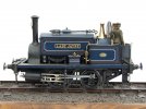
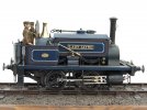
The kit includes an injector (in three parts) and an isometric sketch showing how these parts should go together. I cannot quite relate the result to the injectors I have seen in photos of prototypes so I have looked to a rather lovely model by Dave ( @wenlock ) for inspiration:
Manning Wardle F class 0-4-0 number 719 "Lady Jayne"

DSC_5521.jpeg
I filed down one of the pipe flanges (this had bolt detail on both sides) and put in a pin.

DSC_5522.jpeg
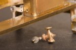
The pin will be glued into the bunker after painting. This will leave the flange at the top a hairsbreadth away from the saddle tank, and so the tank will still lift off. The water feed from the tank will be just above the bottom of the tank.

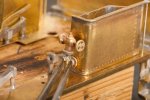
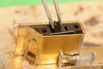
There is also a feed valve to go on the top of the firebox cladding but this is barely larger than the tweezers so it will have to wait until fixing after painting to be photographed.
 
Last edited:
* model built by Dave (much polished brasswork) *

Richard Gawler

Western Thunderer
Two photos of the delightful 'Lady Jayne' by Dave ( @wenlock ) which I am posting here with his permission.

DSCF6666 - Wenlock.JPG

DSCF6667 - Wenlock.JPG
I have found this model, along with those by @Allen M and @Rob R, both helpful and inspiring during my build. The kit provides just one illustration of a completed model, this being the photograph on the lid of the box.

I will be omitting the wheel washing gear but I do want to work up the sanding gear.

I might change the name of my own model. At the moment it is 'Heybridge A' but this sounds a bit like a power station. Something like 'Lady Marion' would have the much same number of letters and spaces and would be fun to work into the fictional history of the line.
 

Richard Gawler

Western Thunderer
have you thought about magnetic micro connectors Richard
Thanks for the suggestion but I think I will be better here with soldering or crimping.

29. Choosing the On/Off Switch and a Fuse

The last big unknown for the electrics has been the on/off switch. I imagine, I could use a mating pair of magnetic connectors to do this, but yesterday a tiny slide switch arrived from Micron.

DSC_5528.jpeg
I actually bought three different styles of switch but this one could have been made to measure. The contacts are rated 0.5 amps so adequate to use as an emergency stop switch as well as for simply turning the model on and off.
 
Last edited:

Giles

Western Thunderer
I've only just read all this - lovely stuff to say the least!
I would be inclined to fit a 0.5A resettable fuse in your power lead for extra protection. I can't remember where I bought mine - I found a supplier via Google - but Micron sells them very reasonably. This is mine before adding heat shrink


I wouldn't consider using magnetic connectors, as they can pick up a bit of wire and short out by accident. I use prewired 1.25mm JST connectors myself, and epoxy them in to both road and rail chassis, as they are nice and small below is a 4mm landrover with its charging socket on the left.


Richard Gawler

Western Thunderer
Hello @Giles, I hoped you would past this way one day. The class F is rather large compared to your Land Rover but finding space for everything inside is keeping me amused and I still don't know where to hide a charging socket. Hence the LiPo battery with its own USB port.

The resettable fuses seem a sensible way to protect the model. The LiPo battery has its own current limiting circuit (I hope!) but if I install an old-fashioned primary battery this really does need some kind of overcurrent protection.

These fuses are semiconductor devices and so the voltage rating is important. I am happier with a radial lead device (and I have the space for one!) so I have found something suitable from Bourns.

Screenshot 2023-12-01 at 07.33.00.png

The datasheet is worth a quick look. The higher the sustain current, the longer the trip time; and these devices have a measurable internal resistance which remains after recovery from a trip. So, I have gone for the MF-R030 which should sustain the load from the heaviest train the loco can haul and has a minimal resistance.
 

Richard Gawler

Western Thunderer
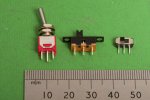
These are the three designs of switches I bought from Micron.

DSC_5531.jpeg
The toggle switch is smaller than the usual ones sold as "miniature". I think I could find a use for it on a small layout or diorama where a control panel is unnecessary. Usual disclaimer, but the service from Micron is very good.
 
Last edited:

Richard Gawler

Western Thunderer
15. Saddle Tank

The saddle tank will consist of a base, folded up at the ends, and a wrapper soldered around the top. Eventually.

View attachment 197802
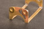
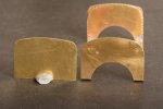
I thought the top corners of the ends (top left) were too abrupt so I rounded them off (top right).

View attachment 197806
I am looking at a photo of 'Sankey' but of course this loco may be carrying a replacement tank (†). I suspect the etch is wrong and my alteration is wrong too.

(†) Photograph of 'Sankey' from SMITHERS, M "Locomotive Builders of Leeds, EB Wilson and Manning Wardle", published in Great Britain in 2018 by Pen & Sword Transport.

And then things went really pear-shaped. The boiler protruded most of 3 mm into the tank, just enough to annoy. I had promised myself I would not take off any more material because the boiler would become difficult to clamp in the machine vice, yet I still had to have a go. I also decided to hold the cutter in a collet instead of the three-jaw chuck, for no real reason except to try out the collet holder. Well, very slowly (and unnoticed), the boiler rotated in the machine vice, taking the working edge away from the cutter, while the cutter worked its way out of the collet. So I took off more material than I intended, and on a sloping cut.

I thought about going cap in hand to Slater’s to see if I could buy a new boiler tube, or asking if someone could roll me a boiler; and then I thought I had better try to put this mess right. I couldn't bring myself to take a photograph of it.

View attachment 197803
My solution was to mill out the crooked edge to try to straighten it up and then put in this strip of 1 mm square brass. This took ages to do, but it was quicker than starting from scratch and it won't show after painting.

View attachment 197805
So, with the rebate for the smokebox rear propped up on a strip of wood to keep the boiler upright, and the inside edges of the tank base fettled very gently, this is the progress so far.

The brass disc top left is the head of a machine screw plugging the first hole for the Roscoe lubricator. I opened out the half-etched hole here before I realised it was in the wrong place. I will go for the location shown in the photo of 'Sankey'.

I forgot to mention, I have decided to not model the boiler bands. When the boiler was still a complete cylinder, I had the option to turn down the diameter to leave the bands showing. But to be honest, they would be almost impossible to see. They aren't included in the kit so perhaps Slater's thought the same.

30. Saddle Tank (completion)

Six weeks on, I have finally finished the saddle tank. This has taken such a long time because I have not been quite sure of what shape it should be, or what detail to provide, or how to fix it onto the model, or indeed how to build it. It has ended up with new ends, a new wrapper, new insides and new details - so really only the inner ends remain from the kit.

DSC_5399.jpeg
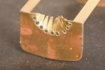
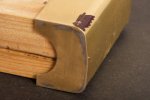
I added new ends and used these washers as a guide to file down the ends to a better radius.

DSC_5408.jpeg
The second new end.

DSC_5410.jpeg
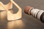
This is my method of making the cut-outs for the boiler.

DSC_5413.jpeg
The drum sanding tool is one of hundreds in a box from "The middle of Lidl", it is more controllable than it looks.

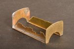
DSC_5416.jpegI tried to reinforce the frame so I could add the wrapper and then cut away the two longitudinals.

DSC_5418.jpeg
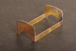
This didn't work out so I rebuilt the frame with some thicker brass strips to hold the ends together - see https://www.westernthunder.co.uk/th...-seeking-wisdom-gained-from-experience.12262/

DSC_5434 (1).jpeg
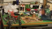
This is the bench after I finally got the wrapper on. Every tool here was used in one way or another though I've forgotten quite why I needed the calculator.

DSC_5439.jpeg
Two bits of wood with a piece of cardboard between them all jammed inside to support the wrapper during drilling.

DSC_5536.jpeg
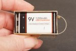
I have enough space for a PP3 battery with two snap terminals and a spare 0.6 mm for the bracket slipped in each side of it.

DSC_5530.jpeg
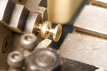
I didn't find the tank filler in the kit but I did find a small brass bolt in the box of household stuff. The handle of the bolt gave me the radius for the top of the filler, and so I only had to machine the shallow filler neck underneath and part off.

DSC_5534.jpeg
So here is the completed tank.

Some locos carried a rack for the fire irons along the top. I have made a couple of brackets from thin brass but they are so fragile I don't think they will survive very well on the layout. So I will miss these off.
 
Last edited:
Top