V2 4 wheel parcel van1/32 and G3

michael mott

Western Thunderer
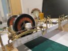
A lot of teeth gnashing today time to reflect a few things, crikey photographs are brutally honest. I'm happy about a few things but not about some others!
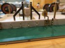
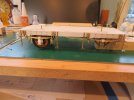
The spring hangers are correctly spaced, but the buffered posts that attach to the ends of the springs are splayed outwards at the bottom ends, and the springs look too flat.
IMG_5005x1024.jpg
The brake shoes seem to be a bit too low

IMG_5003x1024.jpg
This axle-box has to go its lopsided. the springs need to be better, and the brake shoes need to go up about .030" or .78mm.

IMG_5002x1024.jpg

A frustrating day.

Michael
 

michael mott

Western Thunderer
A better day today with some fresh information and more study of the photographs.
Shades of wire handles passed my mind today and a new beginning.
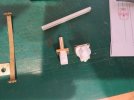
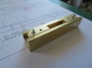
The new direction for the axle-boxes. the back brass piece is now a milled bit of .063" and one piece compared to the oversized three piece soldered assembly.

IMG_5018 x1024.jpg

IMG_5017x1024.jpg
The spring hangers are a sleeved bit of 3/16 O ring which is more correct that the little brass thimble like bits.
IMG_5019x1024.jpg
IMG_5021x1024.jpg

IMG_5022x1024.jpg

The styrene decorative face of the brass axle-box is refined and will look better I think.
IMG_5023x1024.jpg

I will make a new jig for the top leaf with compensation for the lengthened distance between the hangers because of the curve shortening up the flat ones before bending to the correct curve. Doesn't seem like much but it does make a difference.

Michael
 

michael mott

Western Thunderer
Spent a bit of time cleaning up the bench after the disruption caused by the decision to start over a few things.

IMG_5025x1024 - Copy.jpg

First item was to make a new adjustable top leaf spring jig. the pins are changeable for different pin diameters on different models. the pins are locked in place with some 2x56 Allen head grub screws.

IMG_5029x1024 - Copy.jpg

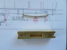
Drawings of the top leaf spring showing the difference between the straight line distance and the length of the curved arc of the top leaf.

IMG_5027x1024 - Copy.jpg

The outside of the pins was set with the vernier caliper then the top spring bent using the same method as the first sets. The centres line up with the drawing.

IMG_5031x1024.jpg

I am pleased with the results.

Michael
 

michael mott

Western Thunderer
Having sorted out the new spring hangers I used the styrene block to hold the new parts while they were flattened and drilled.
IMG_5038x1024.jpg
IMG_5039x1024.jpg
IMG_5040x1024.jpg


IMG_5043x1024.jpg


IMG_5047x1024.jpg


The new top and the rest of the leaves were fettled and drilled for a keeper pin.

IMG_5051x1024.jpg

IMG_5052x1024.jpg

After snipping off the pin to length the square central keeper was slid into place and the springs re assembled onto the sole bars

IMG_5054x1024.jpg

Much better.

Michael
 

michael mott
Western Thunderer
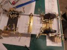
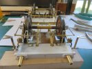
Some progress shots of the reassembly of the undercarriage.

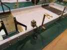
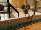
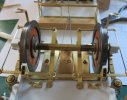
I was able to "raise the brake shoes" by reversing the order of the assembly which also had the advantage of lowering the W irons a little as they were just a bit too high. the brake shoe brackets are held with some home made 00x90 cheese head screws. Instead of the fixed posts being glued with some large flanges they are now threaded into the base sheet, 1x72 with a 25 thou pin to capture the end of the clasping arms. also the stabilizing braces are now held with some home made cheese head screws also 1x72.
The screws will make it easier to take apart for painting.

IMG_5073x1024.jpg

IMG_5074x1024.jpg

The clasping link is now clear of the axle-box and the foot-boards.

IMG_5075x1024.jpg


IMG_5076x1024.jpg

Also using the new draw plate I have remade the bolt/pins that will capture the axle-boxes. When the time comes I can glue on some "nuts" from the same stock.

Capture 5072.jpg

Michael
 

michael mott
Western Thunderer
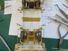
Still working on the brakes linkages and finding it difficult even as things seem to be falling into place.

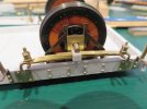
On pages 46 of Russell's book " A pictorial Record of Great Western Coaches (Part One 1838-1913 ) there are two pictures of the clasp Brakes Figure 46 shows the fixed ends of the shoe arms attached to the posts with a cross piece connecting them with what appears to be a U shaped guide hanging down to keep the rods from wandering. and on page 49 fig 52 shows this same condition with what appear to be divergent rods to the outside arms. I have not found a clear picture to show the condition of the linkages at the outer ends so I am speculating how this is done. The triangular situation with a single rod to the central rotating lever does not appear to be the case in this instance.

On the model I have put a couple more posts as a way to keep the outer shoes from wandering about? These are threaded into the base in place of the retaining screws at the ends of the support bars for the fixed ends. Any further help would be gratefully received.
IMG_5098x1024.jpg

IMG_5100x1024.jpg


IMG_5101x1024.jpg


IMG_5102x1024.jpg

I am just trying to get the gear that is hanging below the sole-bars to look correct and logical and that in reality it would work. I have no idea what the way any of these elements fix to the frame. so have devised my own fixing method, as it will not be seen unless the coach is picked up by the "Hand of God" or sits over a reflecting puddle.

Michael
 

Jon Nazareth

Western Thunderer
Some progress shots of the reassembly of the undercarriage.

I was able to "raise the brake shoes" by reversing the order of the assembly which also had the advantage of lowering the W irons a little as they were just a bit too high. the brake shoe brackets are held with some home made 00x90 cheese head screws. Instead of the fixed posts being glued with some large flanges they are now threaded into the base sheet, 1x72 with a 25 thou pin to capture the end of the clasping arms. also the stabilizing braces are now held with some home made cheese head screws also 1x72.
The screws will make it easier to take apart for painting.

View attachment 171029

View attachment 171030

The clasping link is now clear of the axle-box and the foot-boards.

View attachment 171031


View attachment 171032

Also using the new draw plate I have remade the bolt/pins that will capture the axle-boxes. When the time comes I can glue on some "nuts" from the same stock.

View attachment 171038

Michael
Michael
Talking of draw plates. I did look on the internet but couldn't find one that looked as good as yours, there seemed to something lacking in the finish/quality. Have you any more information on the one that you bought?

Jon
 

michael mott

Western Thunderer
Hi Jon I purchased mine through a local supplier who brought it in from the US it is an Italian made, and it was more expensive than the utility ones that they also carry. the specifications for the one I purchased is this one 20 hole hexagonal Draw plate range 3mm-1mm
Here in Canada we end up paying a lot more for some products Given exchange rates and duties and taxes.
Like everything in tools one generally gets what one pays for, If I cannot afford the best tool for the job I gennerally wail till I can afford it or take a different approach. My fingers and knuckles are more important that saving a few pennies on inferior tools, or the frustration of them failing at critical moments.
I am not sure what $68 US would pan out to be in the UK given said exchange rates and taxes etc. I paid more than double that amount where I live because I ordered it as I said through a local shop, If I can support local shops I do because I can also see all the other materials and chat with the owner/manager. The utility versions are approximately the same price as the one I linked to, but the quality was lower that I needed.
I hope this answers your question.

michael
 

michael mott

Western Thunderer
This is stunning work Mi heal.
Thank you John.

More practice with the draw plate and the brass hex stock is getting better, made some .052" across the flats which is very close to a nut to fit a 1"bolt in 1/32 scale. according to my rough calculations. The bore hole is .023" which after cleaning up with the tapered broach sits around .025" which in the real world would be closer to a 3/4 inch bolt so the nut is a bit wide or the bolt a bit too small in diameter. At least they look reasonable on the model.


capture 5105.jpg

Have changed the brake linkage to better reflect what I think is what might have been done on this van. I have removed the posts at the outer ends and have added a connecting strap across the inside ends and added the links to the central crank inboard of the ends of the arms a sort of transition to the triangular truss with the single link that appears in later designs. Mt pretend nuts and bolts holding it all together. I will shorten the protruding bits of bolts before painting.

capture 5110.jpg

Since nobody told me that this is outright wrong and with the current modification I am more comfortable with how it looks.

capture 5109.jpg

Now to sort out the attachment at the centre crank.

Michael
 

simond

Western Thunderer
Michael,

I’m sure your vertical posts were wrong, I’m less sure about your linkage between the levers. This has effectively made the two pull rods and the extra link into a triangular structure, which means that the inner ends of two outer levers must move the same distance (or must swing to one side) and are thus not equalised. This doesn’t seem right to me.

Equally, it does seem that some means of preventing the brake shoes from moving outboard due to the coning is required.

The answer would be to go to Didcot or the SVR and take a photo, if a suitable vehicle can be accessed, and as luck would have it, some of the Folkestone crew & I are going to the SVR in three weeks time.

I will attempt to secure some evidence if it’s possible.

atb
Simon
 

michael mott

Western Thunderer
Simon, Thank you for you informative reply, this is the sort of information I was looking for. I shall put the coach on hold until I get more information which for me seem to be as rare as hens teeth in my neck of the woods. I look forward to your hopefully informative photographs if you manage to take some. I'm sure that there is some detailed information out there somewhere I just have not found it yet.

Michael
 

Jon Nazareth

Western Thunderer
Hi Jon I purchased mine through a local supplier who brought it in from the US it is an Italian made, and it was more expensive than the utility ones that they also carry. the specifications for the one I purchased is this one 20 hole hexagonal Draw plate range 3mm-1mm
Here in Canada we end up paying a lot more for some products Given exchange rates and duties and taxes.
Like everything in tools one generally gets what one pays for, If I cannot afford the best tool for the job I gennerally wail till I can afford it or take a different approach. My fingers and knuckles are more important that saving a few pennies on inferior tools, or the frustration of them failing at critical moments.
I am not sure what $68 US would pan out to be in the UK given said exchange rates and taxes etc. I paid more than double that amount where I live because I ordered it as I said through a local shop, If I can support local shops I do because I can also see all the other materials and chat with the owner/manager. The utility versions are approximately the same price as the one I linked to, but the quality was lower that I needed.
I hope this answers your question.

michael
Thanks you for that, Michael. I shall have another browse through the web. Over here, 16BA nuts are very difficult to come by at a reasonable cost and most of my stock will be taken up securing the hinge straps on my horse box project. Thinking along these lines, a draw plate would be very handy.

Jon
 

simond

Western Thunderer
I did try Espacenet, to see if the original patent was there, but unfortunately not


this one is the DC1 I believe.
 

simond

Western Thunderer
Thanks Graham,

I believe there’s a tool and packing van at the SVR with the same brakes. I’ll try to get some pictures if I can, as I probably won’t get the chance to “do“ Didcot for a while.

atb
Simon
 

Dog Star

Western Thunderer
Well, you did ask for details...

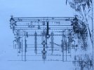
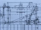
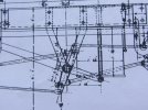
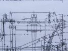
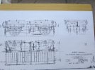
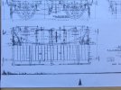
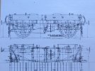
I have two GWR arrangement drawings for NCPS with the Dean external rigging for the brake gear, I shall post photos in two separate posts so as to avoid confusion. Please note that I make no claim in respect of either copyright or applicability to a GW V2 passenger brake van (mind you, details in my drawings do seem similar to your model).

More to the point, the subjects of my drawings look just like the sort of prototype that is calling out for a large scale model.

regards, Graham
 
Last edited:

Dog Star

Western Thunderer
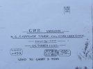
First drawing is for a Narrow Gauge Open Carriage Truck, the drawing is dated 1888, to order 459 for lots 459 and 570.

001.JPG


004.JPG


007.JPG


008.JPG


005.JPG


Apolohies, not much good with the Box-Brownie and 620 film, my drawing copies are black line on white paper and I have no idea as why there is a blue cast to the photos.

regards, Graham
 
Top