You are using an out of date browser. It may not display this or other websites correctly.
You should upgrade or use an alternative browser.
You should upgrade or use an alternative browser.
V2 4 wheel parcel van1/32 and G3
- Thread starter michael mott
- Start date
michael mott
Western Thunderer
Nick that is great, thank you. That will work well.
Michael
Michael
michael mott
Western Thunderer
Thanks for the additional information going to square makes a lot of sense being a forging.
Michael
Michael
michael mott
Western Thunderer
michael mott
Western Thunderer
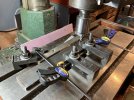
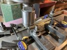
Next step was to get the 3 1/2 dimension accurate, the cut on the tablesaw was cut about.030” oversized because it was apparent from the first piece that there was a little variation end to end. I set up the mill to do this with bars of mild steel stock for stops and clamps.
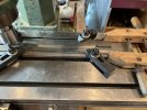
I used a climb cut so that the brass was pushed towards the 3/8” steel backstop.
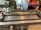
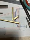
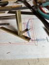
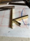
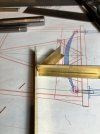
Next the angles have been roughly marked for cutting and fitting before the holes for the various other frame joining angles and W irons etc are done.
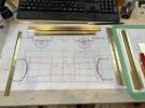
Now the fun part begins.
Michael

I used a climb cut so that the brass was pushed towards the 3/8” steel backstop.

Next the angles have been roughly marked for cutting and fitting before the holes for the various other frame joining angles and W irons etc are done.

Now the fun part begins.
Michael
michael mott
Western Thunderer
First major scewup I set the height gauge to measure the 10.486 length of the sole bars
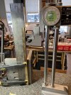
Marked both and cut them when laid next to my ruler they were too short?
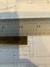
A few naughty words echoed around the room!
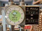
First glance 10.486…… what was happening
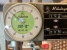
Ah a classic mistake!
So I had to make two new bars it was a good job I had left the mill set up so after bending new bars I milled the new ones. So much work for .1”

Time for tea.
Michael

Marked both and cut them when laid next to my ruler they were too short?

A few naughty words echoed around the room!

First glance 10.486…… what was happening

Ah a classic mistake!
So I had to make two new bars it was a good job I had left the mill set up so after bending new bars I milled the new ones. So much work for .1”

Time for tea.
Michael
Jon Nazareth
Western Thunderer
Er, what was the classic mistake, Michael?First major scewup I set the height gauge to measure the 10.486 length of the sole bars
View attachment 208973
Marked both and cut them when laid next to my ruler they were too short?
View attachment 208977
A few naughty words echoed around the room!
View attachment 208975
First glance 10.486…… what was happening
View attachment 208976
Ah a classic mistake!
So I had to make two new bars it was a good job I had left the mill set up so after bending new bars I milled the new ones. So much work for .1”
View attachment 208978
Time for tea.
Michael
Jon
michael mott
Western Thunderer
hi Jon
Misreading the digital information on the instrument.
Michael
Misreading the digital information on the instrument.
Michael
michael mott
Western Thunderer
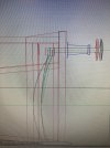
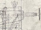
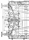
I spent most of the day yesterday studying all the photos and drawings that have been procured. The net result is a bit of a change in the layout of the steel for the frame. The 4wheel Dean coach restoration picture of the frame, and the pictures that Simon posted and one drawing I found on the web helped rework the frame. The frame is only 21 foot 5inches long and from the info In Russell’s booklet to the rework. Withou a definitive drawing of this particular coach built in 1876 I realize there might be some differences or errors. The new layout seems reasonably close and will support the other elements that form part of the Dean clasp brakes.
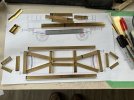
The first basic design.
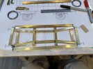
The current layout.
And the updated drawing.
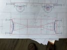
By placing the 2 center angles to create a channel it allows for the bar that connects the coupling hooks. The one part that is still unclear is how a bar that connects the hook at each end works with the traverse leaf springs at each end. The only way I can see is if there is a spring device at the center of the bar.
Michael
The first basic design.

The current layout.

And the updated drawing.

By placing the 2 center angles to create a channel it allows for the bar that connects the coupling hooks. The one part that is still unclear is how a bar that connects the hook at each end works with the traverse leaf springs at each end. The only way I can see is if there is a spring device at the center of the bar.
Michael
Lyndhurstman
Western Thunderer
The RCH drawing here shows the central spring https://www.cs.rhul.ac.uk/~adrian/steam/RCHWagons/images/rch1001.PDFI spent most of the day yesterday studying all the photos and drawings that have been procured. The net result is a bit of a change in the layout of the steel for the frame. The 4wheel Dean coach restoration picture of the frame, and the pictures that Simon posted and one drawing I found on the web helped rework the frame. The frame is only 21 foot 5inches long and from the info In Russell’s booklet to the rework. Withou a definitive drawing of this particular coach built in 1876 I realize there might be some differences or errors. The new layout seems reasonably close and will support the other elements that form part of the Dean clasp brakes.
The first basic design.
View attachment 209128
The current layout.
View attachment 209130
And the updated drawing.
View attachment 209131
By placing the 2 center angles to create a channel it allows for the bar that connects the coupling hooks. The one part that is still unclear is how a bar that connects the hook at each end works with the traverse leaf springs at each end. The only way I can see is if there is a spring device at the center of the bar.
Michael
ChrisBr
Western Thunderer
Michael,
I notice Pete's drawing does not show through connection between the drawbars and whilst I don't know about the V2, the 4 wheel underframe drawing I have from 1891 does not have any connection between draw gear/buffing springs. Certainly 4 plank wagons did not have that connection prior to 1895.
You may be able to make life easy for your self and leave it out....
Chris
michael mott
Western Thunderer
Another discovery that really matters was that my hand held dial caliper that I had been using to measure the 3 1/2 x 9 angle was not zeroed it had a .058” negative reading at the zero position. Which meant that the dimensions were off. I only discovered it when I was carefully lining up one of the angled pieces and noticed that the 3 1/2 “ dimension was too wide when placed over the drawing. Perhaps I should go back to cardboard!
So I also took the opportunity to also tighten up the corner bend now that the pieces are mostly shorter than 4 inches actual I placed each piece one at a time in my old mill vice and with a hammer and a chunk of steel flattened the bend to create a nice tight corner. Then started to put them back on the mill to reduce to the correct .155” dimension. Once those are done I can set up for the 9 “ dimension which is.498”.
It is a good job I am not doing this commercially or I would be seriously considering a different job like ditch digging.
Michael
michael mott
Western Thunderer
michael mott
Western Thunderer
A test to confirm if riveting will work and it does
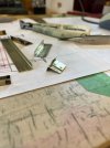
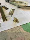
These rivets are 1/32 diameter by 1/4 “ long so I had to snip them to the proper length after inserting the angle thickness is only .018” x 2 the next task is to sort out the domed head for the visible surface on the sole bars. The test was accomplished with a pair of parallel pliers. And the copper rivets are soft enough that it squashes the rivet easily. I am going to make a small hemispherical head that I can glue on one face of the pliers jaws out of silver steel and harden it.
Michael
michael mott
Western Thunderer
I think that making a dome head will be ok a further test with the method described in the previous post, the key will be having the correct amount sticking out to dome.

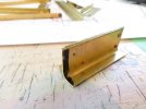
Now to clean up the tooling and have a go at a couple of the challenging joints as tests. The last picture is showing a rivet made from a small 1/4" copper nail. Which is great because I have hundred of them.
Michael


Now to clean up the tooling and have a go at a couple of the challenging joints as tests. The last picture is showing a rivet made from a small 1/4" copper nail. Which is great because I have hundred of them.
Michael

