Rebuilt Crosti 9f

simond

Western Thunderer
Following a post many years back by David LO Smith, I adopted, adapted, and I think, improved the design he suggested. He said it wasn’t his idea anyway, but I think of it in that way.

there were photos, but RMW lost them, and I haven’t built another one since, and sold the loco so can't take any more!

These are my third iteration of David’s sketch. I think they’re the easiest version to make.
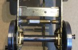
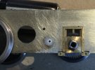
There are simple flanged Tufnol bushes glued in the frames, these are drilled 2mm. They can be any convenient size, but want to be a couple of mm long to support and guide the plungers.

The plungers are 2mm brass rod, centre drilled at one end to form a solder pocket, once the wire is soldered in, they are pressed into a simple plastic top hat bush which insulates the plunger from the spring. The wire simply passes between the coils of the spring. The plungers have to be long enough to touch the wheel back, with a bit of clearance between the top hat bush and the Tufnol bush.

The springs I use are spares from Premier Components couplings.

Where the axle has side play, the whole assembly moves to and fro with the axle, thus maintaining contact, and not “putting the brakes on”. The plungers can be removed from the frames without removing the wheels, which is a further benefit.

DLOS Floating Pickup.JPG

I used Tufnol for the frame bushes because I had some, and it takes epoxy well. The plunger bushes were turned up from some knitting needle
 
Last edited:

Richard Gawler

Western Thunderer
I would put pickups on the tender because they are easier to hide and I expect at least one of the axles can be sprung to improve contact with the rail. Also this approach seems sensible if you have DCC because the decoder can go in the tender. The downside is wiring between tender and loco.
 

spikey faz

Western Thunderer
Unfortunately the presence of compensating beams effectively rules out Simond's admittedly neat solution.
20221115_125406.jpg

Pickups in the tender may be way forward as it's fully compensated.

Mike
 

Ian@StEnochs

Western Thunderer
The plunger can always go on the other side of the axle like this, where it needs to clear a gearbox.
76398980-D16E-44C5-8245-3BB3C705F468.jpegMy solution uses stock brass and plastic tube along with a Slaters buffer spring along with wire and etch waste for the solder tags. No need for special turnings and almost invisible.
16E25FFF-3E19-4EA2-8F88-D1C25EDCE306.jpeg
The method has been describe on a number of WT threads.
Ian
 

Attachments

  • C77ABC18-4D59-4CC0-8476-B2C922DA968E.jpeg
    C77ABC18-4D59-4CC0-8476-B2C922DA968E.jpeg
    198.9 KB · Views: 12
  • F68A4B2E-CC08-46C2-8AE9-504F9B2F6692.jpeg
    F68A4B2E-CC08-46C2-8AE9-504F9B2F6692.jpeg
    204.2 KB · Views: 14

spikey faz

Western Thunderer
Assuming I eventually work out a method of picking up current from the track to propel the Crosti, I thought I'd consider how to stop it as well. In other words: brakes.

The kit castings look OK to me, but I'm never keen on soldering the components to the chassis as I like to have some way of adjusting them. So I've been playing with some Alan Gibson 4mm crankpin components. Pictures below to illustrate what bodgery I'm up to!
20221123_140654.jpg


20221123_140710.jpg
20221123_140813.jpg
20221123_140839.jpg

I'll probably replace the Alan Gibson securing nut with a less conspicuous M1 nut. But I think this will work.

Mike
 

spikey faz

Western Thunderer
As some parts for I want to incorporate into the loco brakes are held up in the post, I've been adding boiler bands instead.

I've used Scalelink for the riveted bands and Slaters phosphor bronze strip for the plain bands.
20221201_085927.jpg

20221201_085941.jpg

20221201_090013.jpg

Close up shots show reveal yet more of the 'adjustments' I've had to make to the boiler/smokebox assembly. It's not neat, and I'm hoping to tidy things up later.

A session with the Crosti sometimes feels like a workout in the Forge of Vulcan!
Mike
 

spikey faz

Western Thunderer
First bit of filler (Milliput) on the firebox and smokebox followed by some primer. More filling to do.

20221204_101024.jpg
20221204_101114.jpg
And then I thought I'd make a start on the ejector.
20221204_121036.jpg
20221204_121223.jpg
I've done a bit of a cut 'n shut on the ejector to get it to line up properly. I've got a bit more pipework to add to it in due course. I've already drilled out the various holes in preparation. Talking of drilling - I also thought the sandbox fillers needed some attention.
20221204_153946.jpg
20221204_154052.jpg
20221204_155520.jpg
20221204_170621.jpg
5mm drill bits from Eileen's Emporium. Far better than the cheap rubbish bits I got off Amazon.

Mike
 

spikey faz

Western Thunderer
Way back in the mists of time I ordered a load of Ragstone parts to enhance the build.

Now, I've found this packet of parts and I'm a bit stumped as to where they go! :eek: I'm guessing on the firebox/grate, but I've not found any pictures either in my books or online. Can anyone help please?

20221205_122403.jpg
Mike
 

mickoo

Western Thunderer
The clue is written on the bag, damper doors and the text 'Standard 6/7' is another clue, I suspect those doors are for Britannia's and Clans.

The 9F has in inverted U shaped ash pan over the trailing axle and is a revised design from traditional ash pans.

Typically the ash pan doors are mounted vertically front and rear and have a combined function, let air in under the fire bed to aid combustion and for clearing out the ash when servicing. The problem with that style, is that hard working engines deposit a great deal of ash which fills the pan and may restrict air flow; worse yet, restricted flow can cause severe overheating of the grate and cause buckling of the fire bars.

The 9F (and some other BR classes....not checked them all) changed that and separated the damper doors (fire breathing) from the ash dump/cleaning doors. The damper doors were mounted much higher up and allowed the pan to fill with ash and not restrict air flow.

The dump doors were moved to the bottom of the pan and are joined together and act as one. Damper doors are (as far as I know) always individual (where front and rear doors exsit) so that you can get the best mix of air to the bed front or rear, even traditional combined doors were operated individually front and rear.

Finding photos of the 9F ash pan doors is near impossible, they're so tight up inside the frames with stays and axles in the way that you can't get a decent view to photograph them. The best I can find is from Loose_Grip_99 on Flickr who works on the GC at Loughborough.

Great Central Railway Loughborough 7th May 2022 by loose_grip_99, on Flickr

This is a view looking aft... I think...I don't have a works drawing for the 9F (I thought I did and something I need to rectify in due course) to confirm, but I think the split brake pull rods are under the ash pan area. The axle nearest is axle #4, the front ash pan door is up behind that big red stay with the oval lightening holes in.

I'm not sure if 9F's were fitted with cannon boxes but that box like assembly with oil and grease lines attached to the bottom looks very much like a cannon box sump, given that axle is directly below the ash pan then it's reasonable to expect some sort of grit/dirt/detritus enclosure even if it's not a full blown cannon box arrangement. Again, I'd need sight of works drawings to find out what that enclosure really is, either way, it's not important to this topic.

The only drawings I have are from the Irwell press 9F book and I've lost my scanner lead so dodgy photos will have to make do.

IMG_1497.jpg

The damper doors are much higher and highlighted in green, the dump/waste doors are on the bottom marked in red.

This NRM photo shows the assembly before fitting but the dump/waste doors are not fitted for obvious reasons, the light weight nature of the dampers mounted higher up are evident.

IMG_1496.jpg

Looking at your castings and comparing with a Britannia ash pan I think they're the two outer ones seen here at high level, aka damper doors, the dump/waste doors are on the bottom and have been removed.

Copyright Nigel Fraser Ker, the website from whence these came seems to have gone now or may have changed address.

_mg_1778.jpg
 
Last edited:

spikey faz

Western Thunderer
The clue is written on the bag, damper doors and the text 'Standard 6/7' is another clue, I suspect those doors are for Britannia's and Clans.

The 9F has in inverted U shaped ash pan over the trailing axle and is a revised design from traditional ash pans.

Typically the ash pan doors are mounted vertically front and rear and have a combined function, let air in under the fire bed to aid combustion and for clearing out the ash when servicing. The problem with that style, is that hard working engines deposit a great deal of ash which fills the pan and may restrict air flow; worse yet, restricted flow can cause severe overheating of the grate and cause buckling of the fire bars.

The 9F (and some other BR classes....not checked them all) changed that and separated the damper doors (fire breathing) from the ash dump/cleaning doors. The damper doors were mounted much higher up and allowed the pan to fill with ash and not restrict air flow.

The dump doors were moved to the bottom of the pan and are joined together and act as one. Damper doors are (as far as I know) always individual (where front and rear doors exsit) so that you can get the best mix of air to the bed front or rear, even traditional combined doors were operated individually front and rear.

Finding photos of the 9F ash pan doors is near impossible, they're so tight up inside the frames with stays and axles in the way that you can't get a decent view to photograph them. The best I can find is from Loose_Grip_99 on Flickr who works on the GC at Loughborough.

Great Central Railway Loughborough 7th May 2022 by loose_grip_99, on Flickr

This is a view looking aft... I think...I don't have a works drawing for the 9F (I thought I did and something I need to rectify in due course) to confirm, but I think the split brake pull rods are under the ash pan area. The axle nearest is axle #4, the front ash pan door is up behind that big red stay with the oval lightening holes in.

I'm not sure if 9F's were fitted with cannon boxes but that box like assembly with oil and grease lines attached to the bottom looks very much like a cannon box sump, given that axle is directly below the ash pan then it's reasonable to expect some sort of grit/dirt/detritus enclosure even if it's not a full blown cannon box arrangement. Again, I'd need sight of works drawings to find out what that enclosure really is, either way, it's not important to this topic.

The only drawings I have are from the Irwell press 9F book and I've lost my scanner lead so dodgy photos will have to make do.

View attachment 175739

The damper doors are much higher and highlighted in green, the dump/waste doors are on the bottom marked in red.

This NRM photo shows the assembly before fitting but the dump/waste doors are not fitted for obvious reasons, the light weight nature of the dampers mounted higher up are evident.

View attachment 175738

Looking at your castings and comparing with a Britannia ash pan I think they're the two outer ones seen here at high level, aka damper doors, the dump/waste doors are on the bottom and have been removed.

Copyright Nigel Fraser Ker, the website from whence these came seems to have gone now or may have changed address.

View attachment 175748
That's brill!

Thanks for such a comprehensive response.

I've got the Irwell press book, but couldn't get my head around the diagram. Your explanation makes perfect sense

Now I know where they're supposed to go I'll see how conspicuous they are on the real thing before deciding whether to use them or not.

Cheers :thumbs:
Mike
 

spikey faz

Western Thunderer
The sandbox fillers plates didn't look quite right. A bit of research showed they had a small flange on each end. Not mentioned in the kit instructions, but add a bit of character (and hopefully distract from my more obvious oversights!). So bent them up accordingly.

20221205_190837.jpg

20221205_192117.jpg
I've also noticed from the above picture there should be a load of rivets on the top of the running plate. I suppose I could glue some punched out rivets on, or shall I bother. Hmm. :rolleyes:

Mike
 

chigley

Western Thunderer
Hello Mike i've searched all my 9f books to no avail but they show hand rail just below the chimney to the right on a crosti only on the smoke box
not sure on 92021 though.

Ken
 

chigley

Western Thunderer
Hello Mike, regarding your pickups glue/ solder a strip of copper clad to the chassis &solder phospher bronze
pickup to it then drill through the frame for the wire similar to MOK, see Len cattley's post 248

Ken
 

Dave Holt

Western Thunderer
In the underneath photo, posted by Mickoo, the blue (to me) flexible hoses are the oil feeds from the mechanical (as opposed to cylinder) lubricator the the axlebox underkeeps (plain bearings on 9Fs). The underkeeps also have a manual filling spout for initial filling and these are also visible.
The can shaped item is the silencer for the boiler manual blow-down. All very similar to a rebuilt Merchant Navy.
Dave.
 

spikey faz

Western Thunderer
Hello Mike i've searched all my 9f books to no avail but they show hand rail just below the chimney to the right on a crosti only on the smoke box
not sure on 92021 though.

Ken
I'm fairly certain the handrail (and associated step) were removed when the Crostis were rebuilt. The Crostis had a hatch in the chimney which was opened to assist with initial firing. Closed once under way. Once all the Crosti paraphernalia was removed the chimney was left open, so no longer required access. Bur thanks for keeping your eyes peeled! :thumbs:
 

spikey faz

Western Thunderer
Many years ago when I used to wizz about in Ford Capris and Ford Cortinas, my weekends were mostly taken up with bodywork repairs. Lots of cutting out of rusty metal and welding in new, with much hammering! Well I've had a bit of a deja vu moment with the Crosti this evening!

I've been merrily fitting boiler bands, working my way back towards the firebox. All OK so far. But trying to align the band that runs across the top of the firebox and down the sides was puzzling. It was only after studying pictures I realised the kit has the mudhole clamps that sit towards the top of the firebox opposite each other. But on the prototype they're offset! :rant:

So, out with the cutting torch aka the piercing saw.

20221208_192118.jpg

20221208_194421.jpg


20221208_195156.jpg
20221208_195726.jpg
I have a feeling the clamps should also be a bit closer to each other, but then that would entail sorting the other side out as well. A step too far? We'll, I'm enjoying a mince pie at the mo, while I decide how to proceed. :)

Mike
 

spikey faz

Western Thunderer
After a mince pie (or two!) I think I'll leave the other side as it is. It's a compromise, but I think I have to draw the line somewhere.

There's also the question mark over the distance between the clamps, but if I alter this it will introduce other small dimensional issues, which I'm keen to avoid.

Mike
 
Top