
You are using an out of date browser. It may not display this or other websites correctly.
You should upgrade or use an alternative browser.
You should upgrade or use an alternative browser.
4mm B.S.L./Phoenix Coach Kits - A Retrospective.
- Thread starter Mike Trice
- Start date


Mike Trice
Western Thunderer
As you say, they are not parallel. Fortunately not a problem in this instance.
I am not aware of any regulation that requires a ruler to have a precision width unless it is specifically sold for precision purposes. If you need to draw parallel lines you require a parallel rule set up or other geometry instruments.. a “ruler” could be triangular in shape and still serve its purpose. Never assume accuracy where it is not required in a product
Bigj
Bigj

Mike Trice
Western Thunderer
It draws a straight line with the ruling pen which is all I require of it.

paulc
Western Thunderer
A couple of strips of masking tape under your favourite ruler or anything else with a straight edge will raise it enough to alow you to use it with a pen . It's an old draughtsmans trick shown to me ( a very young draughtsman at the time ) by an older draughtsman.I havn't abandoned my LMS build, family life got in the way!
With the current spell of cooler weather I decided it was time to attempt lining the side. I debated whether to do the more elaborate panelled style or the later simplified style. Having never lined an LMS coach in my life I opted for the simpler style.
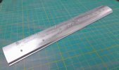
In preparation I prepared a piece of aluminium to act as a practice sheet spraying uPol 8 Acid Etch, Halfords' Red Primer and Gloss Red. The ruling pen is of unknown manufacture but has been honed as per my YouTube videos. Humbrol Gloss Black has been lined, the first one being wider than I wanted. Difficult to show up clearly in a photo:
View attachment 243420
The ruler I am using is as shown. This has the advantage of not only being non-slip but the ruling edge is raised slightly off the model surface being lined:
View attachment 243421
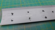
With baited breath I have applied the two horizontal lines to the sides, hopefully in the right place. Definately easier with the sides relatively flat:
View attachment 243422
When dry I will add the yellow lines which hopefully will be more visible!

Stephen Freeman
Western Thunderer
Must be a faulty one if they are not parallel, the thing about width is only of relevance if you doing 7mm scale. Mine (not sure where it is at the moment) is 32mm wide and fits neatly between the rails!
Mike Trice
Western Thunderer
CAUTION: THIS POST MAY CAUSE OFFENCE TO PROFESSIONAL PAINTERS
Tried to separate off some oil from the too runny Humbrol Yellow but is had not settled sufficiently. Fortunately I had a second unopened tin that let me remove the oil before stirring. This worked a treat.
For the heck of it I used a steel rule with masking tape applied as mentioned earlier but did suffer some slippage compared with the cork lined ruler.
This is my first attempt. I say first but I did have to erase some of lines with white spirit and redraw:
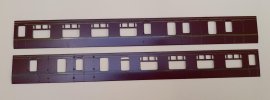
Not perfect by any stretch of the imagination but I think I can live with it:

Tried to separate off some oil from the too runny Humbrol Yellow but is had not settled sufficiently. Fortunately I had a second unopened tin that let me remove the oil before stirring. This worked a treat.
For the heck of it I used a steel rule with masking tape applied as mentioned earlier but did suffer some slippage compared with the cork lined ruler.
This is my first attempt. I say first but I did have to erase some of lines with white spirit and redraw:
Not perfect by any stretch of the imagination but I think I can live with it:
Last edited:

Mike Trice
Western Thunderer
Something I should mention is that in addition to the 4mm kits discussed so far, BSL did produce a couple of O Gauge kits. From memory this was a very limited range however I cannot find any record of what they produced. I seem to recall a GWR Autocoach and possible a B Set. Whether they came as complete kits or not I really cannot remember. Does anyone have further information?
Mike Trice
Western Thunderer
No sooner than I post the above I found an advert for Hobbytime dated July 1973 advertising the following 7mm kits:
LMS Push Pull
LMS Non Corr Composite
GWR B Set
These are listed as complete kits.
LMS Push Pull
LMS Non Corr Composite
GWR B Set
These are listed as complete kits.
Mike Trice
Western Thunderer
Hmm, the loss of posts recently has put me in a bit of a dilemma as to what to post next.
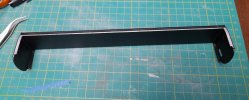
The ends were stuck to the floor pan with standard epoxy then sprayed with uPol8 and Halfords' Matt Black:
The sides were then glued to the floorpan and ends with EvoStik:

Ever get that feeling that things really aren't going as well as they should have done? Part of the reason I will cover in a later post but to cut a long story short I decided to cut my losses and start again.
The body was sprayed with a paint stripper and wrapped in tin foil. This removed a lot of the paint from the sides and dissolved the EvoStik freeing the sides. The ends however were still stuck fast.
They were immersed in Acetone for a period, one end at a time. This softened the epoxy allowing the castings to be carefully pried away:
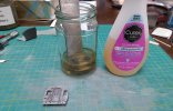
The same was done for the floorpan. I eventually ended up with a kit of parts in reasonable condition:
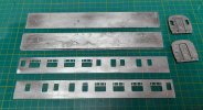
So just as WT was restored to an earlier point in time, so was my model.
The ends were stuck to the floor pan with standard epoxy then sprayed with uPol8 and Halfords' Matt Black:
The sides were then glued to the floorpan and ends with EvoStik:
Ever get that feeling that things really aren't going as well as they should have done? Part of the reason I will cover in a later post but to cut a long story short I decided to cut my losses and start again.
The body was sprayed with a paint stripper and wrapped in tin foil. This removed a lot of the paint from the sides and dissolved the EvoStik freeing the sides. The ends however were still stuck fast.
They were immersed in Acetone for a period, one end at a time. This softened the epoxy allowing the castings to be carefully pried away:
The same was done for the floorpan. I eventually ended up with a kit of parts in reasonable condition:
So just as WT was restored to an earlier point in time, so was my model.
Mike Trice
Western Thunderer
So what went wrong and why did I start again?
In all my dealings with the aluminium parts they seemed to be very accurate until I tried to add the pre-painted sides to the floorpan. They did not fit the recesses.
Hopefully these images show the problem. The floor is sized to the width ofthe ends but due to its thickness the bottom makes the sides lean out:

What is needed is the floor to be tapered so the sides correctly fit in the rebates:
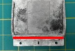
I could have attempted to file these with the sides removed but felt it would be a lot easier with the kit broken down into its component parts.
I also had to shorten one side due to the sequence I assembled everything resulting in a burr which the pre-painted side stopped me from removing. In the end I felt it would be better to start again but leave the painting and detailing until AFTER main assembly.
In all my dealings with the aluminium parts they seemed to be very accurate until I tried to add the pre-painted sides to the floorpan. They did not fit the recesses.
Hopefully these images show the problem. The floor is sized to the width ofthe ends but due to its thickness the bottom makes the sides lean out:
What is needed is the floor to be tapered so the sides correctly fit in the rebates:
I could have attempted to file these with the sides removed but felt it would be a lot easier with the kit broken down into its component parts.
I also had to shorten one side due to the sequence I assembled everything resulting in a burr which the pre-painted side stopped me from removing. In the end I felt it would be better to start again but leave the painting and detailing until AFTER main assembly.
Mike Trice
Western Thunderer
Take two.
The floor was tapered and checked against the ends. It was glued to the solebar unit using JP Quick Weld in an attempt to speed up assembly times. JP Quick Weld is a steel reinforced epoxy whic has the added benefit of being easier to see. This time I camped the two parts together.
Next one of the ends was epoxied in place using set squares to ensure everything was at 90 degrees:
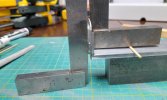
With that set the first side was also epoxied in place:
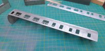
Finally the second side was added and the other end inserted. Use of masking tape helped keep everything together:
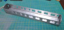
One of the corner joints showing the side correctly recessed. Some extra epoxy has squeezed out along the floor joint but this should be easy to remove later:
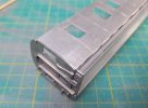
In the words of YouTuber Laura Kampf: "Let glue dry". I will now leave this until tomorrow to set fully.
The floor was tapered and checked against the ends. It was glued to the solebar unit using JP Quick Weld in an attempt to speed up assembly times. JP Quick Weld is a steel reinforced epoxy whic has the added benefit of being easier to see. This time I camped the two parts together.
Next one of the ends was epoxied in place using set squares to ensure everything was at 90 degrees:
With that set the first side was also epoxied in place:
Finally the second side was added and the other end inserted. Use of masking tape helped keep everything together:
One of the corner joints showing the side correctly recessed. Some extra epoxy has squeezed out along the floor joint but this should be easy to remove later:
In the words of YouTuber Laura Kampf: "Let glue dry". I will now leave this until tomorrow to set fully.
Last edited:
Mike Trice
Western Thunderer
Using a pair of dividers I scribed the underside of the roof moulding using the cornice as a datum:
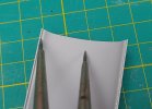
Without adjusting the dividers the same was repeated from the other side:
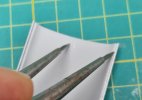
I now knew the centreline of the roof was mid way between the two:

The same was done the other end and a line scribed joining them:
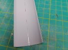
Using this as a reference the ventilator positions were carefully marked out using the supplied BSL drawing:

Where a vent was to go the roof was supported on an offcut of wood, the centrepoint pressed with a compass point then drilled 1.5mm. Resulting burrs were sanded off:

15 holes drilled, only 12 vents supplied in kit. Arghhh! I had no idea whose castings Ron had used so took a gamble and bought some Shell Ventilators Tall Early Type from MJT/Dart. These fortunately proved to be a close match:

With the substitutes to hand the 15 vents were stuck in place ensuring they were all correctly orientated:
Each vent was inserted in its corresponding hole then a dab of epoxy blobbed behind it:
Without adjusting the dividers the same was repeated from the other side:
I now knew the centreline of the roof was mid way between the two:
The same was done the other end and a line scribed joining them:
Using this as a reference the ventilator positions were carefully marked out using the supplied BSL drawing:
Where a vent was to go the roof was supported on an offcut of wood, the centrepoint pressed with a compass point then drilled 1.5mm. Resulting burrs were sanded off:
15 holes drilled, only 12 vents supplied in kit. Arghhh! I had no idea whose castings Ron had used so took a gamble and bought some Shell Ventilators Tall Early Type from MJT/Dart. These fortunately proved to be a close match:
With the substitutes to hand the 15 vents were stuck in place ensuring they were all correctly orientated:
Each vent was inserted in its corresponding hole then a dab of epoxy blobbed behind it:
Last edited:
Mike Trice
Western Thunderer
Amoungst the posts that were lost I showed a useful tool I bought from Amazon. It is a set of chisels from 0.1mm to 2mm wide including handle. I have found this really useful to scrape out errant glue from cavities that would be difficult to reach otherwise:

This is with the 2mm blade fitted:
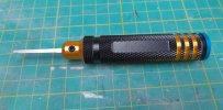
This is with the 2mm blade fitted:
Mike Trice
Western Thunderer
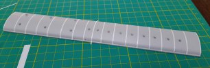
The roof has been sprayed with uPol8 and the ribs added from strips of electrical tape. The strips are still overlong to allow for any shrinkage prior to trimming.
Are the strips in the right place? Unlikely. Are they perpendicular to the roof? Doubtful.
I am hoping that when I am happy (if I ever am) that a coat of non acid primer will fix them into place more permanently.
Are the strips in the right place? Unlikely. Are they perpendicular to the roof? Doubtful.
I am hoping that when I am happy (if I ever am) that a coat of non acid primer will fix them into place more permanently.
Mike Trice
Western Thunderer
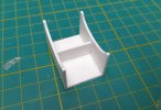
Heath Robinson device to check alignment of cross bands:

Mike Trice
Western Thunderer
MkII design. With added clearance for any existing vents!
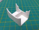
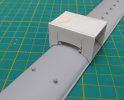
Given up trying to use electrical tape. All this faffle makes me wonder how others achieve these ribs on LMS roofs?
Given up trying to use electrical tape. All this faffle makes me wonder how others achieve these ribs on LMS roofs?