Brettell Road, 1960s black country (ish)

adrian

Flying Squad
The easiest is to keep them parallel to the backscene however if you don't (as I haven't) then the roof can actually become a little bit of a problem area. Theres 2 main ways to address this, Keep the pitch of the roof the same and cut the top at an angle. Or keep the top parallel to the rest of the building and adjust the pitch. My personal opinion is that the latter is the better option. The pitch on my acorn building is significantly different from the left end to the right end.
Beautiful work and given the quality of results and photos it's hard to disagree with you.
 

Jim smith-wright

Western Thunderer
One aspect of making Brettell Road longer is that the original fiddleyards will need to be replaced. As such the opportunity will be taken to increase their length from four feet to five which means I can increase the cassettes from three feet long to four and a half. Any bigger than that and cassettes start to become unpractical and a bit sketchy anyway.

jinty-at-brettell-road-nov-22.jpg

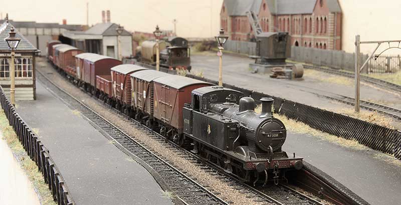
A four and a half feet long freight train on Brettell road.

94xx-at-brettell-road-nov-22.jpg

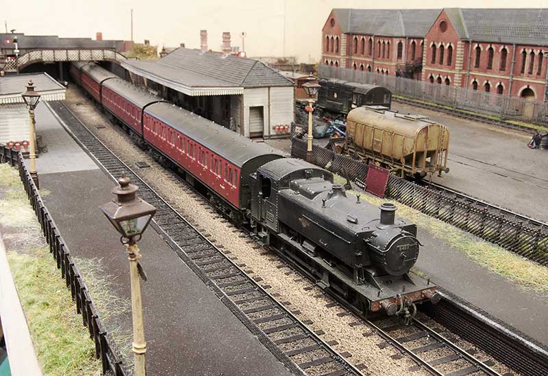
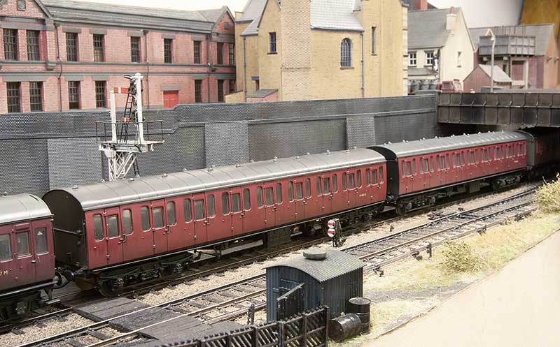
A four coach passenger train. When I built this originally one of the (then 3 coaches) wasn't finished as I hadn't detailed up the underframe yet and just swapped the bogies. This was due to Brettell Road's first outing coming up (Scaleforum 2018) and it never got moved from the 'roundtuit' list since.

new-coach.jpg

But when another cheap coach popped up I decided to get this little train ticked off so they were both detailed up together. Leaving just one thing outstanding...

brake-pipes-LMS.jpg

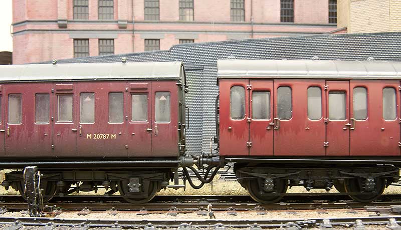
...the brake pipes. I admit to not using working ones on my wagons, as the layout is principally a shunting one, but as this is a fixed rake of coaches why not? I came up with the original idea for this back around 2005 and articles appeared in update and MRJ. The original update article can be downloaded from here - https://p4newstreet.com/articlePDFs/Update42pipes.pdf. Where I have differed from my original article is to have one long pipe for the vac pipe and another long pipe for the steam heat pipe I figured 4 short pipes would just stick together in a clump! So theres a magnet on the end of the pipe that connects to a magnet in the bufferbeam. All simple stuff really but it does mean that the coaches and their pipes have to be couple up or the pipe will drag on the track and no doubt get stuck!
 

michael mott

Western Thunderer
Jim Wonderful portrayal of the buildings, I have to agree with you on the roof line issues the changing pitch can be a bit tricky though as the sheet is twisted, compensating with the tile strips makes a lot of sense. How do you deal with the twist?
Love the shot with the chap walking away.
Michael
 

Jim smith-wright

Western Thunderer
Thanks
It's all a bit heath Robinson really. I start with a rectangle based in the longest pitch then just pop it in place and mark the other end. I use either 2 or 1mm card. To secure it I glue the long and lower edges, then when set the the short and top edges.

The pitch change is the easy bit. It's the odd shapes that's a faff
 
Last edited:

Jim smith-wright

Western Thunderer
For all of my lifetime, certainly my time aware of railways, mainline diesel locomotives have been powered by a diesel engine driving electric traction motors. However the Western region was never really one to follow what everyone else was doing and invested heavily in Diesel hydraulics. Of those the largest class and the only one to fit into the type 3 category were the Hymeks of which I missed out on. When I was born there were half a dozen still in service and they were withdrawn before I had transitioned from a 4 legged human to a 2 legged one. So they are all a bit alien really.

Apart from the transmission (and the idea of a mainline loco with gear changes) there were other things that were a bit odd. Why wasn't the radiator fan housing central? Why didn't they use no.1 and no.2 ends, Instead of having A and B and why was the radiator at the back not the front like everything else? Despite all the weirdness they were attractive little locos though so when a Heljan one popped up cheaply on Ebay (described as having intermittent running) I put in a cheeky bit and as no one else did, a Hydraulic is coming to Brettell Road.
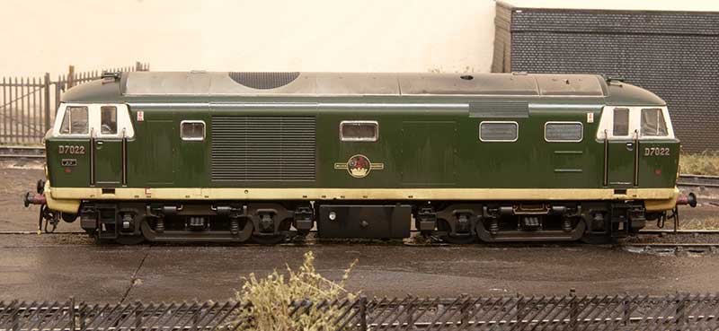
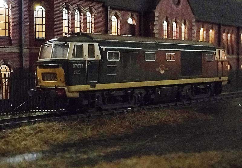
D7022-@-Brettell-Road-4.jpg

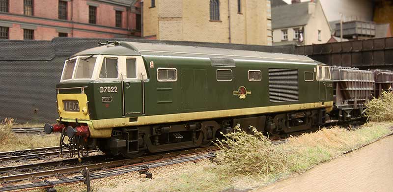
Not having any 00 track I didn't investigate the reported running problems but the Heljan wheels were filthy and having swapped them out for some Alan Gibson ones no running issues were encountered. This model is one of Heljan's early efforts and in terms of getting the shape right still one of their best. However there are a few tweaks that can be done. The roof horns were broken so they were replaced with Markits brass ones. The buffers were a bit naff so those were replaced with Lanarkshire Models ones. The numbers and builders plates are from Shawplan/Extreme etches. The rest is really down to working with what Heljan give you. The bodyside windows are flush glazed but not flush enough so they were cut out and remounted. The cab side and door windows are fine but I did add the droplight strips from 10x10 microstrip.

Not much to do on the chassis really - I added the mileometer on the leading axle of the B end (left) and I thought the pipework on the bogie frame at the A end was a little too fine so replaced it with wire.

D7022-@-Brettell-Road.jpg

This is the A end from the other side. As I was doing an early batch loco I carefully cut off the headboard clips and touched in the yellow. The windscreens were also not flush enough but it was easier to just replace them with clear plastic cut to shape. Oddly the glazing on the headcode box (yes i know the headcode is wrong for the train) was too flush so this was replaced as well. Windscreen wipers are again from Shawplan and the brake pipes are from Hornby (the loco wasn't supplied with any). I also remounted the tank under the bufferbeam and added a little pipework. To avoid confusion when it comes to DCC I've followed the diesel electric convention and set the fan end as forward.
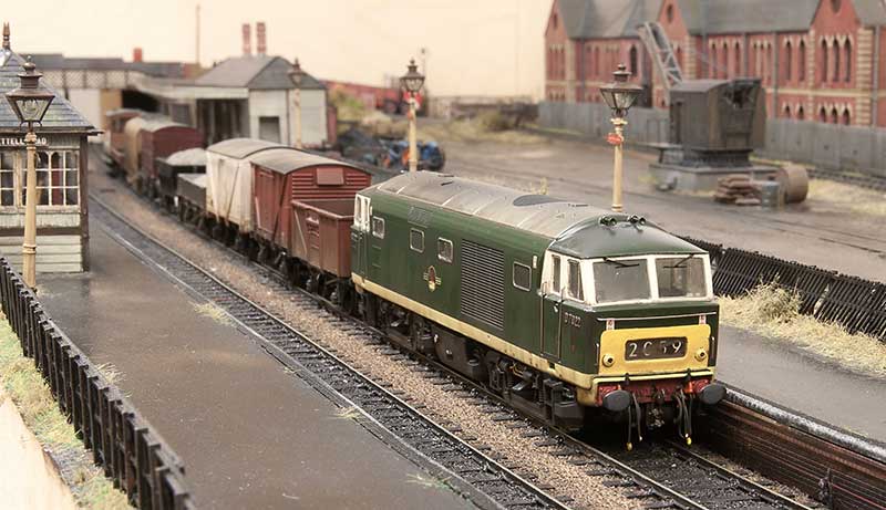
D7022-@-Brettell-Road-2.jpg

The model is weathered to look new but not 10 yards from the factory new. Im aiming for a few months and bear in mind the layout is set in autumn. There seems to be a tendency among modelers to weather Hydraulic locos to look an absolute state and most of them did end up that way in real life. So basically washes that I've pretty much cleaned off again as best I can before light dustings of track colour and roof dirt. This was followed with streaks from AK interactive spilt fuel and grease before finally the obligatory rain effect. Diesel locos tend to have characteristic weathering which is unique to each class (something which a lot of professionally weathered locos you see seem utterly devoid of). Class 24 to 27 have the water stain from the roof, just inboard of the fan. Class 50s have 3 leaks that run down the fuel tanks, class 20s have an odd direction for the staining deposits from the exhaust and class 31s have the oil leaks through the bodyside at floor level. Hymeks have this too but not as much and from my research only later in their (short) lives. They do however have a distinctive leak on the fuel tanks and this seemed to have been from new.
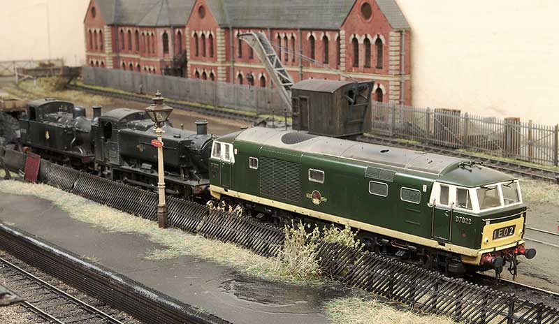
lickey-bankers.jpg

Any reason for D7022? Ive always had an affinity for the Lickey incline and these 3 locos were all regulars on banking duties over the years. The Hymeks went there much later than Brettell Road is set and were the second class of diesel to work the incline. The first being English Electric type 3s (class 37). A lot of Hymeks worked the Lickey but the initial ones were D7021-D7025. In his book, A life on the Lickey, Pat Wallace talks about them and mentioned that early on they preferred to have the A end facing north (up the gradient). If a loco turned up the wrong way round it was sent to Worcester to be turned on the triangle. He doesn't give any detail on why this was the case but you could lock out first gear in a Hymek and the equipment cabinet for this was in the A end. The locos definitely had first gear locked out while on this duty. This was because the change from first to second gear was right in the range where trains were banked and they could snatch. The Hymeks having only one engine were a little worse for this than the Warships and Westerns.

One little anecdote Pat also mentions concerns the 17th January 1968 when a kitten was discovered in the engine room of D7025. He was adopted and named Hymek (of course). He crops up again 10 days later when he had managed to hide himself in the bogie of D7022 and refused to come out. It was reported that Hymek the kitten did 4 trips up the Lickey!

D7022-@-Brettell-Road-3.jpg
 

Jim smith-wright

Western Thunderer
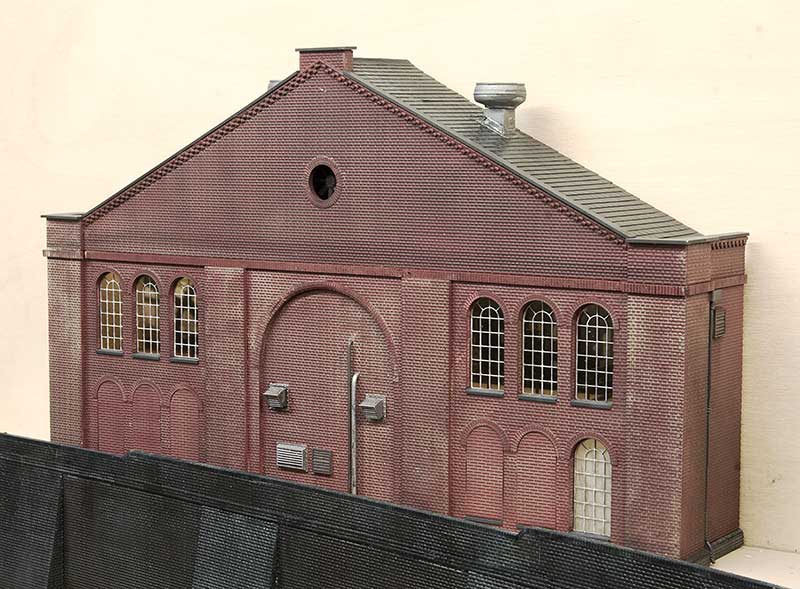
lion-building.jpg


This is my latest building for Brettell road and likely to be the last but one physical model building for the layout. I have plenty more buildings to create yet but as those will be on the backscene they will need to be illustrated instead.

As usual it takes its inspiration from a local structure and this time its the Lion Health building in Stourbridge. Or at least a bit of it. Construction is the same as the others featured recently so I wont go over old ground again. Before it was a health centre the Lion Health building was an Ironworks built by Foster, Rastrick and Company in 1821. John Urpeth Rastrick was originally from Morpeth and had previously constructed an early railway locomotive for Richard Trevithick in 1808. The company would continue to produce steam engines as well as proving machines for chain cable, saws, mills, and boilers. It also produced structural components for buildings, bridges and gas works and in 1825 it listed railway components in a catalogue of products including rail, sleepers and chairs. Its fourth locomotive, Agenoria, was built for the Earl of Dudley's railway and it survives to this day at the National Railway Museum. The company fared far worse than Agenoria and it was officially dissolved on 20 June 1831 and it was absorbed into the Stourbridge Iron Works of John Bradley & Co. James Foster was already the major partner (John Bradley was his half brother) and after 1832 James became the sole owner.

The site went through several more owners but they kept the name John Bradley & Co. (Stourbridge) Ltd. The first was when, in 1919, the Stourbridge Iron Works were sold to a company owned by Edward J. Taylor and then in the interwar period, N. Hingley & Sons Ltd took over but it still continued to trade under the John Bradley & Co name until 1963. The company was finally wound up in 1966 but the Stourbridge Ironworks continued as a rolling mill within the F.H. Lloyd Group until 1982. The building became derelict was nearly destroyed completely due to a fire in 2004. In 2012 it was renovated to become Lion Health which opened in 2014. In 2009 a couple of urban explorers managed to get in and took some pictures, these can be seen here Report - - Foster, Rastrick and Company, Stourbridge, West Midlands May '09 | Industrial Sites

What have lions got to do with any of this?

In 1829 Foster, Rastrick and Company built a locomotive for the Delaware & Hudson Canal Company in the USA and this loco, Lion, or rather the Stourbridge Lion is noted to be one of the first foreign built locomotives to be operated in the United States, and one of the first locomotives to ever operate outside Britain. The locomotive performed well in its first test in August 1829 but was found to be too heavy for the track and was never used for its intended purpose of hauling coal trains. Parts of this locomotive also survive and are on display at the B&O Railroad Museum in Baltimore.

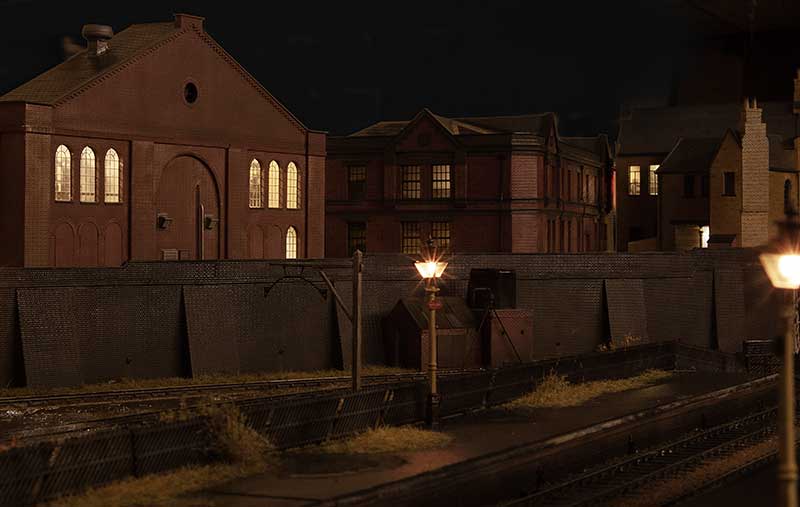
BR-dark-nov-22-b.jpg

A view from the platform. I think i'll tone the lighting down a bit more.

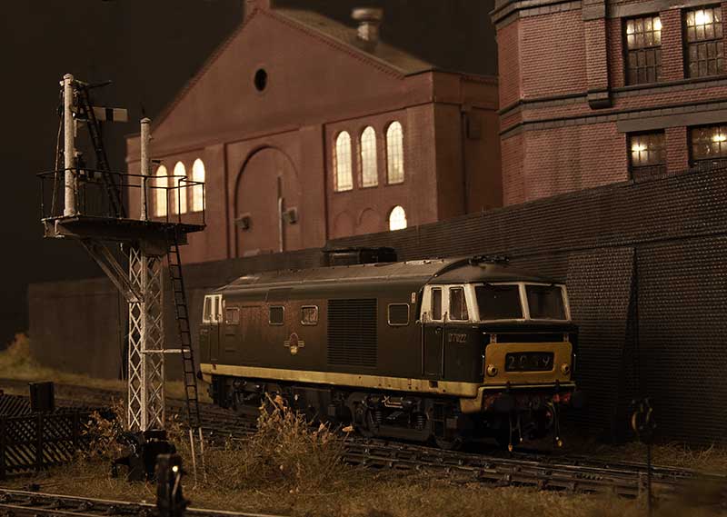
D7022-@-BR-21-nov-22.jpg

The recently completed Hymek trundles past.

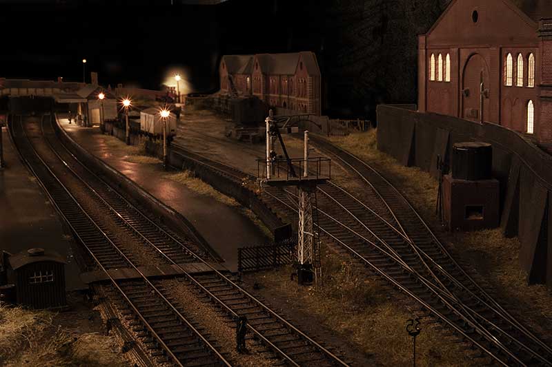
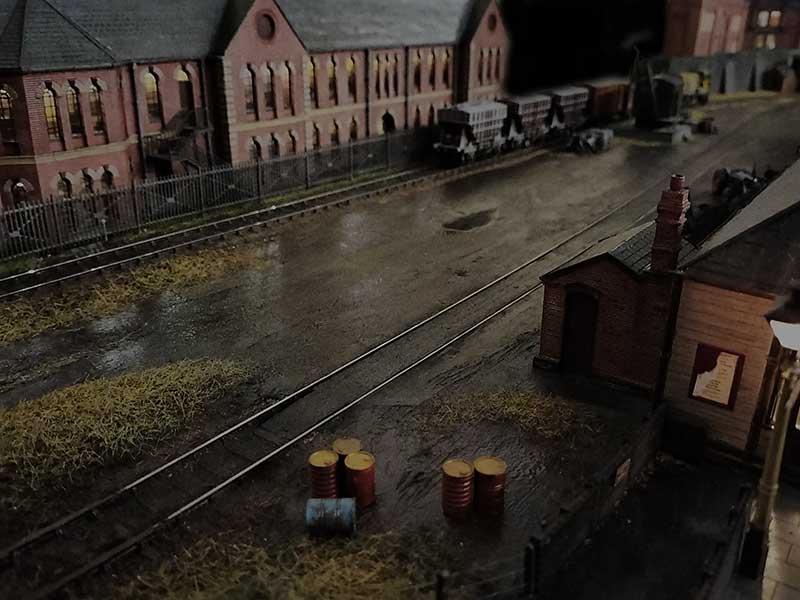
Below are a couple of overall layout shots which I think captures the wet look I'm after. The last one from my phone so apologies for the lack of depth of field.

BR-dark-nov-22.jpg

BR-dark-nov-22-c.jpg
 

PaxtonP4

Western Thunderer
As a Black Country boy your layout brings back memories. I used to employ a Consulting Engineer, in the latter part of my career, who took up offices in the refurbished Higgs building. I visited that building many times.
 

Jim smith-wright

Western Thunderer
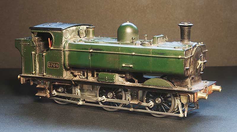
One of my slow burning projects has been a humble little 57xx tank. A combination of the old (But essentially quite good) Mainline body and a High Level Kits chassis but with a bit of twist.

Iain Rice wrote about these back in MRJ 61 and 62 using a similar route, in his case using a Perseverance chassis as that was what was available around the time, and I would urge readers to refer to this as a start point.

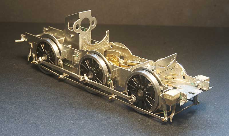
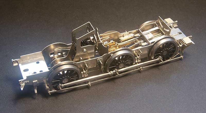
The High Level chassis

57xx-chassis.jpg

Like all of Chris' chassis this was a joy to build (this is my 4th of his chassis kits now, who would have thought it?) I opted to use Brassmasters bearings which may have messed the alignment up a little as I found I needed to mount the break gear 1 mm lower than as supplied. Strangely though the buffer height seems fine. I differed a little bit from the instructions by making all of the brake gear removable. The rear rods that go behind the wheels seems to trap the rear axle in place as supplied.

Eagle eyed viewers might spot something little odd and yes, you've guessed it - I've gone off piste again.

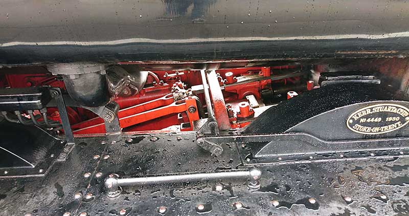
prototype-57xx-motion-2.jpg

prototype-57xx-motion-1.jpg

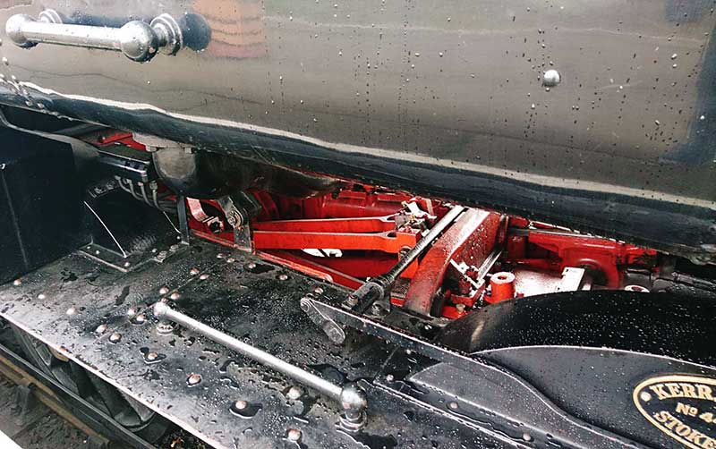
A couple of prototype pics from the Severn Valley. Personally i though the inside motion was pretty obvious looking at the real thing and while there is a representation of it in the High Level Kit I wanted it to move.

57xx-tank-motion.jpg

So this is a mish mash of bits - Brassmasters 4f bits at the axle end and Finney GW bits at the front. The GWR version of inside motion seems much simpler that the midland one and the hardest part of this task wasn't putting it all together but getting it in place. Being a small loco theres not a huge amount of wiggle room.

57xx-tank-rough-fit.jpg

The body is essentially good, you could say extremely good for its time. The obvious stand out bit of weirdness was the top of the dome but nothing a spot of filing can't sort out. It did come with a separate main handrail and some wire ones around the bunker but they were all a bit heavy so i replaced those along with those handrails that were moulded on. I reduced the size of the front wheel splasher by cutting it off and gluing it back on, The width of the cut being all you really need. I didn't feel the need to fiddle with the centre and rear ones. While on my 94xx I replaced all the pipework under the tanks in front of the cab with this model I thought it was good enough as is, although I have cut away the 'holes' as per Iain's article. Theres a bit more detailing to add to the footplate yet and the lower pipework will need to be replaced.
 

AJC

Western Thunderer
I opted to use Brassmasters bearings which may have messed the alignment up a little as I found I needed to mount the break gear 1 mm lower than as supplied.

Having one of these in the pile, and just about finished a Jinty, I wonder whether your brake positioning issue relates to the wheels. Squinting closely at your pictures, the shape of the centres looks like the Midland pattern rather than the GWR version and that does (going on the figures in the Gibson catalogue and on direct comparison with the products) has a longer crank throw by 0.8mm which would account for the difference. I only know the difference because I had to replace a wheelset on the Jinty and having brought the right wheel, realised that the others were 'wrong'. It's not noticeable, but would explain the apparent discrepency.

Adam
 

Jim smith-wright

Western Thunderer
Having one of these in the pile, and just about finished a Jinty, I wonder whether your brake positioning issue relates to the wheels. Squinting closely at your pictures, the shape of the centres looks like the Midland pattern rather than the GWR version and that does (going on the figures in the Gibson catalogue and on direct comparison with the products) has a longer crank throw by 0.8mm which would account for the difference. I only know the difference because I had to replace a wheelset on the Jinty and having brought the right wheel, realised that the others were 'wrong'. It's not noticeable, but would explain the apparent discrepency.

Adam
It's not that. The centre of the brakes were higher than the center of the axles. I probably should just compare a brassmasters bearing with the high level one I guess
 

Overseer

Western Thunderer
It's not that. The centre of the brakes were higher than the center of the axles. I probably should just compare a brassmasters bearing with the high level one I guess
Isn’t the uncentred brakes a GW design quirk? Someone who models GWR should be able to fill in the details but I think the earlier panniers had the brake blocks above the axle centre line while later ones had them a few inches below. Very few GW locos had the brakes centred on the axle centre line, there must have been some logic to the design decision.
 
Top