Peter Insole
Western Thunderer
I do hope no-one is under the impression that every part of this project is carefully considered and executed? Of course, there are times when I might like to think that is indeed the case... but to be absolutely honest, it really is quite the opposite, as I just seem to lurch and stumble from one success to another!
It is such a pity that when I started on the water level gauge cocks back in February 2021, (post #309) I had dutifully copied the one forlorn remnant on "Wren", (and eventually, after much frustration, managed to make something workable!) only to realise that some of the parts are not of the original pattern, and the earlier style tube protectors would require smooth, round, rather than hex nuts! The subject was briefly revived in October 2022, (#602) but returned to the backburner again when no further reference material could be found.
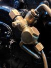
In the above image, only the central, body and valve lever section are to the original design, whereas the union nut and rather oddly excessive drain/blowdown cock/huge lump of gunmetal are LMS replacements!
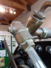
Below is another view of the type (albeit on Beyer Peacock "Dot") that I can be fairly confident was similarly fitted to all the locomotives throughout LYR ownership.
Despite still being unable to locate suitable detail, or (preferably) specific patent drawings for the gauge glass protectors, I finally decided that I would have to take a risk and adopt an experimental approach, just to see what happens!
It might be worth mentioning again that, for very practical reasons, all the brass fittings on the model are made from the nearest available size sections. I have tried wherever possible to restrict the amount of cutting and filing down to the vital, and "character" shapes. This works reasonably well for much of the time, but can occasionally present a problem. The chamber (junction?) section of the gauges were drilled out of 11mm brass round bar, and the attached "nuts" were drilled through for a 6mm clear plastic tube. All fitted well enough, and while they may not be absolutely precise in scale, I have been fairly content that they look the part.
I was dreading the prospect of having to chuck away some previously good stuff, and make two brand new nuts, both with such slender margins providing yet more chance to mess up the centre drilling! As can be seen in the second photo, (above) there is a section of hex machined out of the nut, with rather horrifyingly little metal at the centre of the flats! That detail caused me way too much anxiety, and I was still deeply unsure of what to do about it - right up to the point of clamping some more 11mm bar in the vice!
Mind you, in one way it did help just a touch that, and to my complete and utter amazement, when pre-drilling the 6mm bore, the bit didn't appear to have wandered - and at the first attempt too! On the other hand, that fact alone probably added a little more pressure not to screw the following tasks up?!
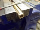
Yet again, I was deeply unhappy about having to shape a hex form purely by eye... but I couldn't see any other practical way to accomplish it.
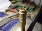
By the time I reached this stage, my courage had failed. I know that at least another millimetre should have been taken off each facet - especially noticeable as the external diameter of the body had to be slightly reduced again to a sliding fit with the internal dimension of the new brass tube (sold as 11mm - but with the usual, and appropriate as it turned out, disclaimers)!
I am somewhat relieved that the errors should not really be evident on the assembled article though, as they will be hidden inside the protector tube - but they do have to be fully functional for later access purposes.
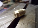
Even more surprising to me was that the second go went through well enough too. I still really can't believe how lucky... and how relatively painless that exercise became?! The only profundities uttered throughout the entire process were when, on at least four occasions, I dropped either the object, or the needle files on the workshop floor... but, (sigh) that's the normal nowadays!
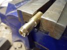
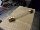
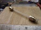
After a bit of fettling and fiddling about, all the parts finally came together:
Hurrah!
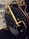
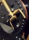
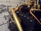
It was very pleasing to find that although it is close fitting, that by shifting the tube fully upwards to the limit and then subsequently downwards on the nuts, the hex sections are exposed just sufficiently in order to be slacked off with a spanner, and then undone with fingers until they run up inside the tube. The whole assembly, complete with "glass" can therefore be removed or replaced - although it admittedly is a bit fiddly, being quite a tight fit between the cocks, and at just under one third of full size!
Cutting a long viewing slot, and adding a small grub screw into the brass tube would be the next tricky tasks.
It will also be very interesting to see how well the glass tube, and indeed the water level inside are visible if I then follow the general arrangement schemes by providing only a single cut out?
Pete.
It is such a pity that when I started on the water level gauge cocks back in February 2021, (post #309) I had dutifully copied the one forlorn remnant on "Wren", (and eventually, after much frustration, managed to make something workable!) only to realise that some of the parts are not of the original pattern, and the earlier style tube protectors would require smooth, round, rather than hex nuts! The subject was briefly revived in October 2022, (#602) but returned to the backburner again when no further reference material could be found.

In the above image, only the central, body and valve lever section are to the original design, whereas the union nut and rather oddly excessive drain/blowdown cock/huge lump of gunmetal are LMS replacements!
Below is another view of the type (albeit on Beyer Peacock "Dot") that I can be fairly confident was similarly fitted to all the locomotives throughout LYR ownership.

Despite still being unable to locate suitable detail, or (preferably) specific patent drawings for the gauge glass protectors, I finally decided that I would have to take a risk and adopt an experimental approach, just to see what happens!
It might be worth mentioning again that, for very practical reasons, all the brass fittings on the model are made from the nearest available size sections. I have tried wherever possible to restrict the amount of cutting and filing down to the vital, and "character" shapes. This works reasonably well for much of the time, but can occasionally present a problem. The chamber (junction?) section of the gauges were drilled out of 11mm brass round bar, and the attached "nuts" were drilled through for a 6mm clear plastic tube. All fitted well enough, and while they may not be absolutely precise in scale, I have been fairly content that they look the part.
I was dreading the prospect of having to chuck away some previously good stuff, and make two brand new nuts, both with such slender margins providing yet more chance to mess up the centre drilling! As can be seen in the second photo, (above) there is a section of hex machined out of the nut, with rather horrifyingly little metal at the centre of the flats! That detail caused me way too much anxiety, and I was still deeply unsure of what to do about it - right up to the point of clamping some more 11mm bar in the vice!
Mind you, in one way it did help just a touch that, and to my complete and utter amazement, when pre-drilling the 6mm bore, the bit didn't appear to have wandered - and at the first attempt too! On the other hand, that fact alone probably added a little more pressure not to screw the following tasks up?!

Yet again, I was deeply unhappy about having to shape a hex form purely by eye... but I couldn't see any other practical way to accomplish it.

By the time I reached this stage, my courage had failed. I know that at least another millimetre should have been taken off each facet - especially noticeable as the external diameter of the body had to be slightly reduced again to a sliding fit with the internal dimension of the new brass tube (sold as 11mm - but with the usual, and appropriate as it turned out, disclaimers)!
I am somewhat relieved that the errors should not really be evident on the assembled article though, as they will be hidden inside the protector tube - but they do have to be fully functional for later access purposes.

Even more surprising to me was that the second go went through well enough too. I still really can't believe how lucky... and how relatively painless that exercise became?! The only profundities uttered throughout the entire process were when, on at least four occasions, I dropped either the object, or the needle files on the workshop floor... but, (sigh) that's the normal nowadays!


After a bit of fettling and fiddling about, all the parts finally came together:
Hurrah!


It was very pleasing to find that although it is close fitting, that by shifting the tube fully upwards to the limit and then subsequently downwards on the nuts, the hex sections are exposed just sufficiently in order to be slacked off with a spanner, and then undone with fingers until they run up inside the tube. The whole assembly, complete with "glass" can therefore be removed or replaced - although it admittedly is a bit fiddly, being quite a tight fit between the cocks, and at just under one third of full size!
Cutting a long viewing slot, and adding a small grub screw into the brass tube would be the next tricky tasks.
It will also be very interesting to see how well the glass tube, and indeed the water level inside are visible if I then follow the general arrangement schemes by providing only a single cut out?
Pete.
Last edited:


 )
)


