7mm Mickoo's Commercial Workbench

mickoo

Western Thunderer
I'd be a bare faced liar if I said alcohol was not consumed in the inception of this :cool:

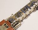
Replacement assembly for a MR Kirtley Goods, it's a proof of concept design, can you do the whole lot as one, can you make it warp free and make it smooth.

IMG_5541.jpg

IMG_5543.jpg

IMG_5544.jpg

It needs a final coat of primer as the witness one has been rubbed down to look for defects.
 

mickoo

Western Thunderer
Back at the day job, the ROD is progressing, it's still all a jumble of bits in close proximity but it's getting there.

I kept the kit smoke box door as I remembered I had a bundle of scale bolts kicking around, so the door fastener was drilled and the hex bolts fitted; I also replaced the kit buffers with some spare LNER ones.

I have to confess to not looking forward to hand making 25 washout plugs but it'll have to be done at some point.

IMG_5545.jpg

IMG_5546.jpg

IMG_5547.jpg

IMG_5549.jpg

Because I messed around with the frame jog and footplate, the end result was that pretty much all of the splashers had to scratch built to fit.

The front steps are fixed to the footplate, on the real engine and in the instructions they're supposed to be fitted to the outside motion bracket, unfortunately that traps the crosshead in place; I also made new backing plates to match later day BR(E) engines.
 
Last edited:

mickoo

Western Thunderer
Couldn't you print these?
Interesting question, yes and no.

Yes you can print them and if they were buried like most washout plugs then you'd get away wit it, in fact you'd be better off printing the whole fire box with them already fitted and in hindsight that's what I should have done.

No in that half of then stick out a long way and would be very fragile.

The end product will be 1.2 mm brass rod with a square filed on one end, these are inserted into 1.8 mm recesses which have a 1.2 mm hole in the base to hold the rod.

The other option is 1.0 mm square rod with thin bore tube soldered over the outside (but leaving a bit of square exposed) and then turned down to 1.2/1.4 mm OD and popped in the holes.

Image1.jpg

Oh and I forgot I have to make five washout clamp covers as well.
 

Dog Star

Western Thunderer
The end product will be 1.2 mm brass rod with a square filed on one end, these are inserted into 1.8 mm recesses which have a 1.2 mm hole in the base to hold the rod.
Mick,

I can relate your description above to the lowest row of plugs, not to the row adjacent to the handrail which look like each plug is screwed into a button welded on to the outer firebox casing. Anyone explain why the plug mountings near to the handrail seem to be flush with the cleading?

regards, Graham
 

Genghis

Western Thunderer
Interesting. It looks like the mudhole covers changed design later in life.

Would these be any use?
IMG_5534.jpg

Actually looking at the cruel close up, perhaps not. They were designed for use with thick castings. Might still be quicker to fettle. When I built a Director I threw the LNER washouts in the bin and resorted to square wire. Another item for the upgrade list..............
 

Osgood

Western Thunderer
Mick,

I can relate your description above to the lowest row of plugs, not to the row adjacent to the handrail which look like each plug is screwed into a button welded on to the outer firebox casing. Anyone explain why the plug mountings near to the handrail seem to be flush with the cleading?

regards, Graham
Reckon the upper plugs are fitted into the end of big external firebox top stay flanges, Graham.
The cropped images below, from the excellent Gorton Tank book, show either a 2-8-0 boiler or something very similar:

IMG_8679.JPGIMG_8678.JPGScreenshot 2023-12-16 at 08.27.18.png
 

LarryG

Western Thunderer
The GC 2-8-0 looks very nice and, like any well built model, is too good to paint. I know your painter will do a superb job, but observers will be looking at the paint job and not your workmanship, if you see what I mean. But of course, models have to be painted.

Much of my time used to be spent making other peoples locos 'saleable' by squaring them up with the lining and making oval splashers circular...!
 

mickoo

Western Thunderer
The GC 2-8-0 looks very nice and, like any well built model, is too good to paint. I know your painter will do a superb job, but observers will be looking at the paint job and not your workmanship, if you see what I mean. But of course, models have to be painted.

Much of my time used to be spent making other peoples locos 'saleable' by squaring them up with the lining and making oval splashers circular...!
Cheers, I was asked today at the Bucks Hill meet why I clean them up, simply because with a bright surface you can see a lot of imperfections long before paint is added, especially on curved surfaces.

Warren will use his old blunt crayons on this one ;) :cool: , plain black and weathered, but that's no excuse not to have a neat and square model underneath.
 

mickoo

Western Thunderer
Interesting. It looks like the mudhole covers changed design later in life.

Would these be any use?
View attachment 204123

Actually looking at the cruel close up, perhaps not. They were designed for use with thick castings. Might still be quicker to fettle. When I built a Director I threw the LNER washouts in the bin and resorted to square wire. Another item for the upgrade list..............
Close but not quite, I've had a few hours in the car today driving and think I've come up with a (reasonably) simple, workable solution.

I am going to have to go backward a little but before moving forward but it should all work out in the end.
 

Dave Holt

Western Thunderer
Whatever class of loco that boiler was for, it appears to have a sloping backhead, which probably limits the possibilities. Also, the regulator works in the upper quadrant, which might preclude the larger locos? It's certainly not for a C13 tank, as they had vertical backheads, although the arrangement of the backhead fitting is very similar indeed.
Dave.
 

paulc

Western Thunderer
Cheers, I was asked today at the Bucks Hill meet why I clean them up, simply because with a bright surface you can see a lot of imperfections long before paint is added, especially on curved surfaces.

Warren will use his old blunt crayons on this one ;) :cool: , plain black and weathered, but that's no excuse not to have a neat and square model underneath.
I asked a professional builder the same question , his reply was that his customers preferred to see nice shiny models in the progress photos that he sent them otherwise he wouldn't have bothered.
 

Osgood

Western Thunderer
Whatever class of loco that boiler was for, it appears to have a sloping backhead, which probably limits the possibilities. Also, the regulator works in the upper quadrant, which might preclude the larger locos? It's certainly not for a C13 tank, as they had vertical backheads, although the arrangement of the backhead fitting is very similar indeed.
Dave.
Well spotted, appears to be a shorter boiler (3, not 4 cross stay mounts and the dome is not far enough forward), but in all likelihood it shares the same design of firebox crown stay mountings as the ROD boiler.
 

mickoo

Western Thunderer
Well spotted, appears to be a shorter boiler (3, not 4 cross stay mounts and the dome is not far enough forward), but in all likelihood it shares the same design of firebox crown stay mountings as the ROD boiler.
Might be an export engine?
 

mickoo

Western Thunderer
Final throes of the ROD build, these will be the last fully assembled photos, further work requires partial strip down and then once done, total strip down, deep clean and bag up for paint. Still to do topsides, tender fall plate and two angles on the rear division plate, on the engine, clothing band clamps and reversing lever reach rod; that can't be fitted until the weight shaft and cranks are fitted inside the frames. Finally new vac pipes and stands need scratch building to replace the broken white metal ones.

The final chore is inside motion, most of it will need hacking from various parts scavenged from the spares bin and some scratch building to complete.


IMG_5550.jpg

IMG_5551.jpg

IMG_5552.jpg

IMG_5553.jpg
 
Last edited:

mickoo

Western Thunderer
Someone asked for some details on the inside motion and how it all goes together.

The ROD is slightly different from previous inside motion sets I've done, double drop links and over and under eccentric rods to clear the 2nd axle.

You're on your own getting anything like the real thing; so in bearded men in garden shed mode, it's a mish mash of parts nailed together. You need a couple of parts from Laurie Griffin miniatures (LGM), specifically the expansion links (though these are not 100% accurate-later) and the drop links. Unfortunately there's only two drop links on each sprue so you need to buy two sets and bin the rest.

The drop links are universal which means no lower bearing, this allows you to adjust the length to suit your engine. These I cut to length and file a half round slot in the bottom end, then add small lengths of 1.5/1.0 mm OD/ID tube to make the lower bearings. The expansion link only has one bracket to hold a singular drop link, it should have two but what you get is better than nothing. Buried deep down in the frames the lack of bracket isn't that noticeable if you place it closest to the frames.

The other LGM part is the piston rod tail end shaft and clevis, the casting has an offset piston rod (a legacy from MR/LMS slide valve set ups, LGM may do a centrally aligned piston rod but I've not seen or used one yet) so it needs cutting off, the shaft drilling out centrally and a new piston rod fitting.

You also need some new etched eccentric rods with forked ends, the forked end is offset 60/40 so you need to make sure the offset are correct to get the expansion link to hang straight and true. The main bearing has a enlarged boss on one side, that needs to be opposite the fork offset.
Finally some bespoke eccentric sheaves and etched overlays with cosmetic ribs and webs hold the eccentric rods in place. a quick test fit shows it clears the 2nd axle and all hangs straight.

Next step is the weight shaft arms (again with small bore tube bearings) and counter balance arm with weight. the arms can now be measured to fit exactly between the drop links and weight shaft in the frames. After that I'll have an accurate position for the piston rod clevis and bearing shaft, then the motion bracket can be made and fitted.

0dbd2411-a236-455b-b016-49b3e04ba4c2.jpg

IMG_5554.jpg

IMG_5556.jpg
 
Top