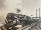
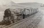
Rebuilt Crosti 9f

mickoo

Western Thunderer
I don't think it matters one jot which tender you're modeling, I suspect all the intermediate buffers are the same, the clue being in the name BR Standards.

All the BR tenders I've managed to find in a quick five minute search all appear to have exactly the same intermediate buffer.
 

spikey faz

Western Thunderer
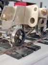
I now appear to have a rolling chassis. :)

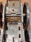
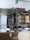
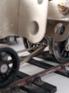
The MOK driving wheels are split axle with a taper-pin to hold the two axles halves together. Even once the pins are shortened, clearance is still tight on the front cross member that holds the pony truck. So I've moved the pony truck pivot forward a bit and removed some of the crossmember metal. Pictures will hopefully explain! ;)

20220608_152643.jpg
20220608_184554.jpg
20220608_200324.jpg
20220608_200331.jpg
I must say I'm quite pleased how the chassis works. No motor yet (that's on order), but just pushing the chassis to and fro reveals no binding or issues. So, ten out of ten to the designer. :thumbs:

Mike
 

spikey faz

Western Thunderer
Mike,

why not just shorten the tapered pin?

OzzyO.

I have! Just enough to get a rolling chassis but will subsequently be shortened further. However the front axle is really close to that crossmember and I don't want to end up with a taper pin that's too short. Once it's filed down there's no going back!

Hope that sort of makes sense.

Mike
 

OzzyO

Western Thunderer
Mike,

you can buy tapered pins for the job that you are doing I would think that they would be metric (1:50 taper) DON'T try to use imperial ones as they have a taper of 1:48.

I got some a good while back it may have been from Items mail order.

HTH

OzzyO.

PS you can't really shorten the pin too much without cutting into the axle. The pin will still only fit one way round.
 

OzzyO

Western Thunderer
Mike,

I think that you may want to have another look at the spacing between the centres of the middle and L/H lamp bracket (R/H in your photo).

OzzyO.
 

Dave Holt

Western Thunderer
Yes, when the upper lamp iron was moved down (and sideways) due to overhead electrification concerns, the middle iron on the footplate was also move sideways to align with the upper one so that the code with these two irons still had them directly above one another, just not on the loco centre-line.
Dave.
 

spikey faz

Western Thunderer
Yes, when the upper lamp iron was moved down (and sideways) due to overhead electrification concerns, the middle iron on the footplate was also move sideways to align with the upper one so that the code with these two irons still had them directly above one another, just not on the loco centre-line.
Dave.
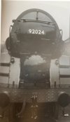
Ah! Thanks for clarifying that for me Dave. Makes perfect sense to me. :thumbs:

Mike
 

OzzyO

Western Thunderer
Mike,

it's not the position of the centre lamp bracket that I'm talking about, the position of that lamp bracket is as Dave has pointed out. It's the position of the side lamp brackets that I was on about, with a bit of luck these pictures should help clear it up.

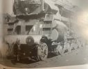
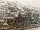
92024 1955, side lamp brackets inside of handrail for side steps.
92024 1955.JPG

92024 1960 side lamp brackets outside of hand rail for side steps.
92024 1960.JPG

92026 1966 side lamp brackets outside of hand rail for side steps.
92026 1966.JPG

92027 1955 side lamp brackets inside of handrail for side steps.
92027 1955.JPG

Looking at the pictures it looks like one of two things happened the side lamp brackets got moved when the pre heater was removed of when the centre lamp bracket was moved.
I've had a look for 92021 with the top lamp bracket moved to the side of the door but with no luck yet.

OTB

OzzyO.
 

spikey faz

Western Thunderer
Those are great photos OzzyO - Thanks for sharing those:thumbs:

You'll have to bear with me on the subject of these lamp brackets as I'm still a bit confused! Are you saying that one or more is in the wrong place? I'm quite happy to move 'em but the pictures I've got of 92021 seem to show them where I've soldered them accordingly. I am aware that the buffer beam rivets don't line up 100% which is probably down to my incompetence! This might make the brackets look a bit out of place?

Mike
 

OzzyO

Western Thunderer
Mike,

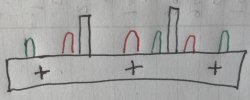
I'm not saying that your lamp brackets are out of position just that it's very unusual for them to be positioned that way. A very bad sketch showing the normal positions.
The black uprights are the frames, first lamp iron positions in red. The second lamp iron positions in green.
IMG_5724.JPG

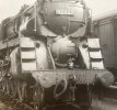
Looking at this photo of 92021 the lamp irons are in the first position. 195592021 1955.JPG

But in this photo the lamp irons are in a hybrid position, with the two outer lamp irons in the red position and the middle one in the green position. Also this loco doesn't not have the large centre step between the frames under the smokebox. 1967
92021 1967.JPG


I'm going to send you a PM soon.

ATB

OzzyO.
 
Last edited:

spikey faz

Western Thunderer
Aw, thanks chaps. That's all so brilliant! I hadn't realised what a minefield something so innocuous could turn into a minefield. My current thoughts are to move the centre bracket further over to the sideframe, as per Dave's picture of 92021 of 1 Aug 64.

Mike
 
Top