7mm Rob's workbench - Gladiator J6

Rob Pulham

Western Thunderer
Still making slow but steady progress in between with the J6.

The tender is now coaled and ready for weathering. I plan to weather the loco and tender at the same time so that I get them looking the 'same'

52084346094_d3d1e38ccf_h.jpg


52084125253_aa9b804945_h.jpg


52084125168_d4fa4a2834_h.jpg


52084125048_ca1417cf4e_h.jpg


I almost forgot, I dropped the LG Miniatures fire irons in some dilute metal black which has given them a nice 'rusty' appearance.
 

Rob Pulham

Western Thunderer
This week has seen more work on the J6 most of which isn't really photogenic as it's been to do with assembling and fitting the inside motion which isn't quite there yet.

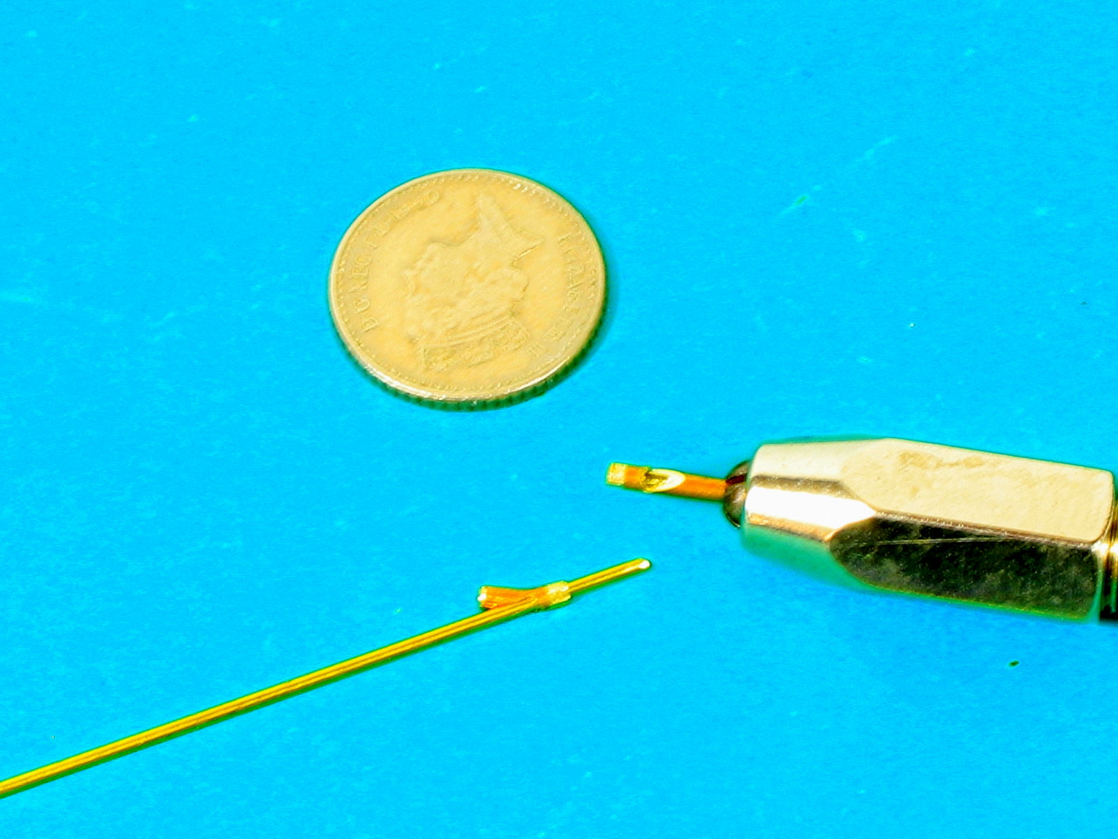
In order to assemble much of the motion I needed some pin so I decided to turn some taper pins from 0.9mm nickel rod.

52091504310_8fc885b2c4_c.jpg


Having touched up the tool of a stone and got myself into a bit of a rhythm, I soon had a dozen or so ready. I only remembered to take a picture after I had fitted most of them...

Whilst pondering on aspects of the fitting of the motion, my thoughts turned to the remaining jobs to be done and one of those is sand pipes.

A quick check on Laurie Griffin and Ragstone site's didn't reveal much in the way of sand pipes so I decided to make my own.

I started by checking sizes on the GA and settled on some 0.8mm rod for the pipe itself. I had a length of microbore tube that fitted over it and used that to make the body of the fitting where the steam pipe attaches.

52091024218_6e7e8819d4_h.jpg


I started by filing a notch in the pipe such that with a slight bend to the remainder I could feed the 'pipe' through the sort end giving me an angled branch.

52091545470_0ef11c20ce_b.jpg


Next I filed an angled flat on the end of the tube to create the other branch of the fitting.

52091003806_8d92da804c_h.jpg


Some home made nuts/unions and 0.45mm beading wire for the steam pipe, completes the job - x four of course

52091250004_8031923d6b_h.jpg
 

Rob Pulham

Western Thunderer
A bit of a milestone was reached in the Pulham household last night. I have been tinkering for a number of days with the inside motion, getting it all to fit in the frames. I had to mill the inner side of each crosshead to clear the eccentric straps etc. so they are now handed and I also had to enlarge the centre section of the motion bracket to allow the assembled eccentric rods, expansion links etc to pass through it. Then came the final job of determining the length of the connecting rods and cutting them to length.

Once they were cut and tried in place the length was right but they wouldn't fully rotate because I hadn't made the slots in the motion bracket deep enough. Much filing and testing ensued but I didn't seem to be getting anywhere and then I realised that because of the constant assembly/disassembly for testing, I had the frames upside down. What I was viewing as the top was in fact the bottom so I had been adjusting the wrong side. More filing and test ensued and I got there in the end.


Having tested the pistons successfully with the valve parts resting outside the motion bracket I put it all together inside for a further test.


Rob Pulham

Western Thunderer
It's alive at long last. I fitted the final parts of the motion, and the motor and gave it a test run. Thankfully it ran straight off without any issues with the motion itself but the chassis had an odd wobble on the rolling road when running forward that wasn't evident when running in reverse.

Initially I wasn't concerned, because running on my rolling road is never as smooth as it is on track. But then I noticed that the middle driver had a pronounced wobble and thought that the screw had worked loose. When I lifted if off the rolling road and felt the wheel, it felt loose but when I tried to tighten the screw it barely moved and the wheel was still loose. This was a bit dismaying because this is the axle that I have spilt for the motion.

My first test was to swap the two centre wheels over to see if I had the same issue and much to my relief, both tightened up as they should and the wobble went away.


Rob Pulham

Western Thunderer
A couple of weekends ago I was demonstrating Loco building at the Stainmore Railway Model Railway show. I took along the chassis for the J6 and had it running on the rolling road all weekend. Besides giving the motion a really good bed in it attracted a lot of attention.

So much so that I plan to make up another chassis with inside motion for my demo stand.

On the back of a great weekend out I decided to see if I could crack the construction elements of the J6 last week.
The remaining jobs were.

Fit glazing
Add Milliput to the back of the balance weights to make them solid rather than just an etched front.
Fit the sand pipes
Fit the remaining linkages between the brake pull rods and the brake cylinders
Fit some Frame extensions under the boiler between the front pairs of wheels to hide the rear of the wheels – following Tony Geary’s lead.

52173801378_bd82bf5b6c_h.jpg

Balance weights, I added a coat of primer to bled it all in before final paint and weathering.

52174040384_88e68a29c1_h.jpg

The first bit of the brake linkages

52173800803_66ac5aa54c_h.jpg

Front sandpipes and Frame extensions. Before fully soldering them in I tested the frame extensions at one side by tacking them in and the seemed perfect. But the chassis mustn’t have sat down properly because I noted while testing for clearance on the rear sandpipes that they need trimming down a bit.

52174805869_a2052614a3_h.jpg

Rear sandpipes. I had to fit the tops of them very close to the frames to avoid the injector pipework but I got there after two or three adjustments.

52176753880_e61c4ff9d3_h.jpg

52176269921_38e0a51b2d_h.jpg

Last but not least a couple of shot of the remaining brake linkages. Although soldered at the rear the ends of the rods are a loose fit in the turnbuckles so allowing removal of the brakes.
 

Rob Pulham

Western Thunderer
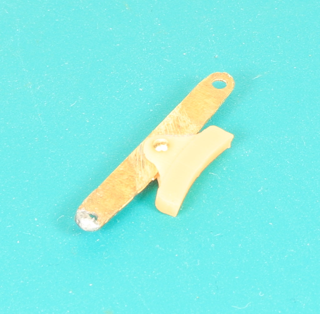
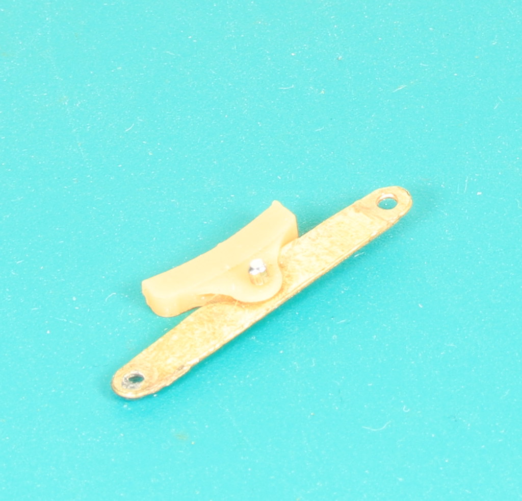
I wasn't really happy with how far away from the wheels the brake shoes needed to be to ensure that they didn't short. I rew up some brake shoes in Fusion and a friend kindly printed them off for me.

Today I had the chance to test fit one of them. After checking that I hadn't messed up and that the etched hanger would go between the flanges. I bit the bullet, unsoldered the etched overlay and cut of the brake shoe from the hanger.

The next question was how to attach the printed brake shoes to the hangers. I hoped to have the shoes free to move and after considering and discounting various options which involved superglue I settled on a dressmakers pin and short length of microbore tube soldered to the pin and then filed down.

52207340431_b6ff295308_b.jpg


52206333002_fa1ae32e4f_b.jpg
 

Richard Gawler

Western Thunderer
Please Rob, how have you fitted the crankpin screws into the wheels? It looks like there are some bushes inserted into the wheel centres.
 

Rob Pulham

Western Thunderer
Hi Richard,

On this particular loco, the crank pins are the standard Slaters supplied 12ba cheese head screws that I have countersunk into the wheels

IMG_0001.JPG
IMG_0002.JPG
The supplied crank pin bushes are filed down so that they are just thicker than the coupling rod.

On other locos I have tapped the hole and the crank pin bushes 10BA and used 10BA countersunk screws instead. My personal jury is still out as to which I prefer. Certainly on crank axles for outside motion I would replace the pin with a 10BA screw so that I can used a second tapped bush to assist with retaining the return crank.
 

simond

Western Thunderer
I also use 10BA screws from the rear of the wheel, inserted after tapping the wheel, and with a small dollop of epoxy on the thread. The excess fills the hole where the head is, and if there's more than enough for that, the excess gets carved off when set.

I have heard of people soldering a wire into the slot in the screwhead to prevent issues with return cranks unscrewing. I thought this was overkill, and didn't bother on my Duchess or Garratt.
 

Richard Gawler

Western Thunderer
Rob, this is exactly what I have have done on my 'Nellie' loco, except I have embedded the heads of the 12 BA screws in Araldite. This is advised by Jim McGeown in his instructions for the kit. I managed to tap three out of four screws into the wheel centres, and pretty perpendicular too, the fourth one just went round and round . . .

The arrangement seems a bit naff as a first impression but this is clearly what all users of Slater's wheels get so I must get used to it! A part of me wants to drill out the holes in the wheel centres and stake in some kind of brass bush but I don't have the tools to do this with the necessary accuracy and repeatability.

I must have done something right because my chassis ran with just one little tight spot after I put the side rods on.
 

Dog Star

Western Thunderer
The arrangement seems a bit naff as a first impression but this is clearly what all users of Slater's wheels get so I must get used to it!
Not "All" users...

A part of me wants to drill out the holes in the wheel centres and stake in some kind of brass bush but I don't have the tools to do this with the necessary accuracy and repeatability.
What you describe is what is available with the range of 7mm driving wheels from the S7 Group, see this webpage and search for S7855.

To go with the wheels there is a range of crank pins, crank pin bushes and retaining collars (to secure coupling rods). OK the wheels come with S7 axles and there are ways of swapping them. Yes, the wheels are sold exclusively by the S7 Group and solely to members of the group... there are (legal) ways of overcoming the constraints imposed by tax regulations (the S7 Stores Officer is a member of WT).

regards, Graham
 
Last edited:

Richard Gawler

Western Thunderer
Food for thought, and maybe next time for me. There is at least one S7 modeller (from 'Love Lane') in the North East Essex group too.
 

Rob Pulham

Western Thunderer
I got to fitting the rest of the 3D printed brake shoes to the J6 brake hangers today and then refitted them onto the pull rods. I don't think I have shown the loco sat on the body since it's pretty much complete. Just a few final bits like wiring it up and testing it before painting the chassis and weathering the whole thing

52214868912_240d1c947f_h.jpg


52215890068_c7d6059b8a_h.jpg


I also fitted the back head a couple of weeks ago but didn't take any photos

52214869142_f66dba7b4e_h.jpg


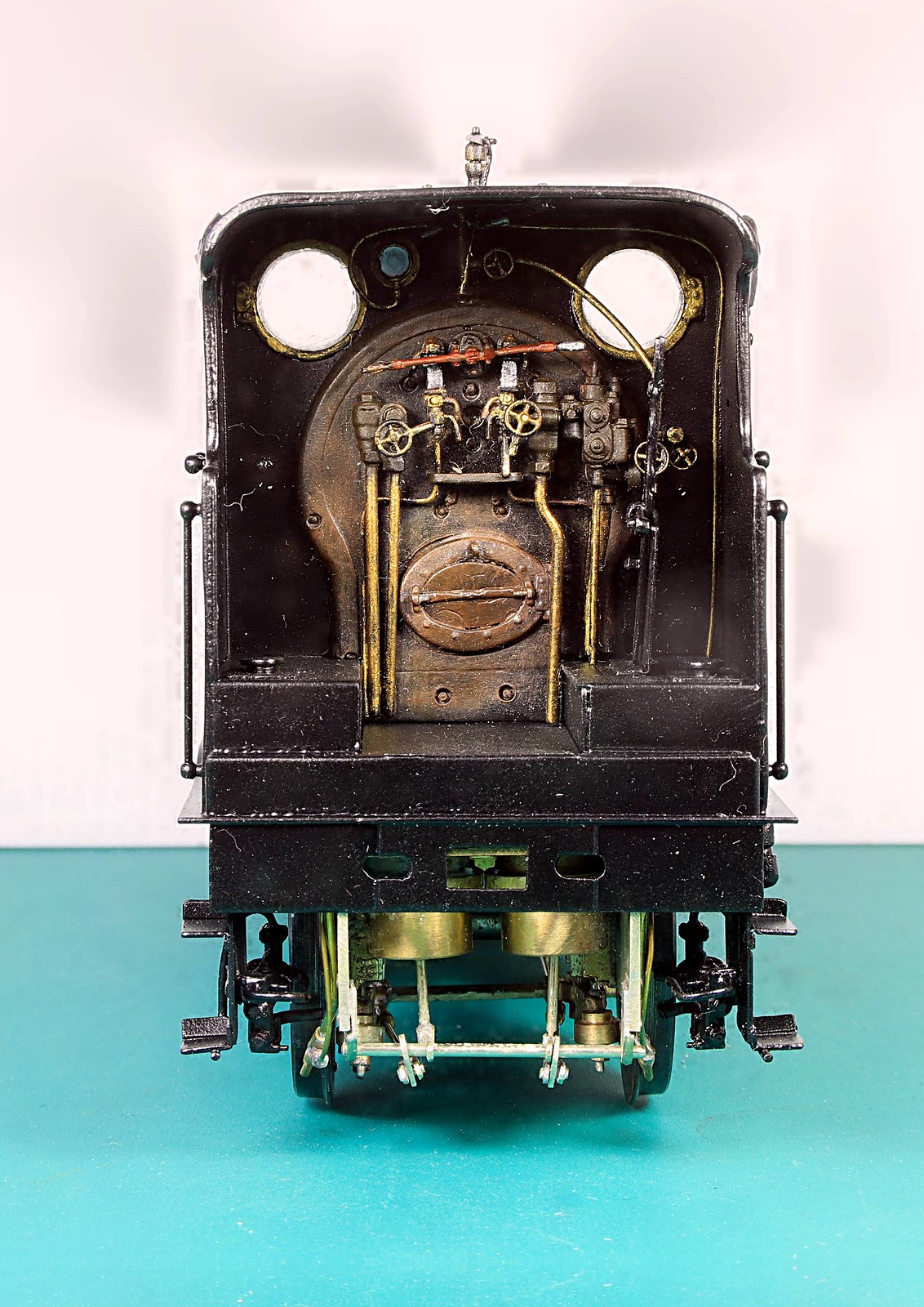
The rear view shows that making up the brake cylinders was worth it as they are quite visible when the loco is separated from it's tender.
 

Rob Pulham

Western Thunderer
Over on this Heybridge Railway thread I mentioned that I was about to wire up the tender for the J6 with Slaters Plunger pickups and I offered to take photos as I went along. I have put them here for continuity.

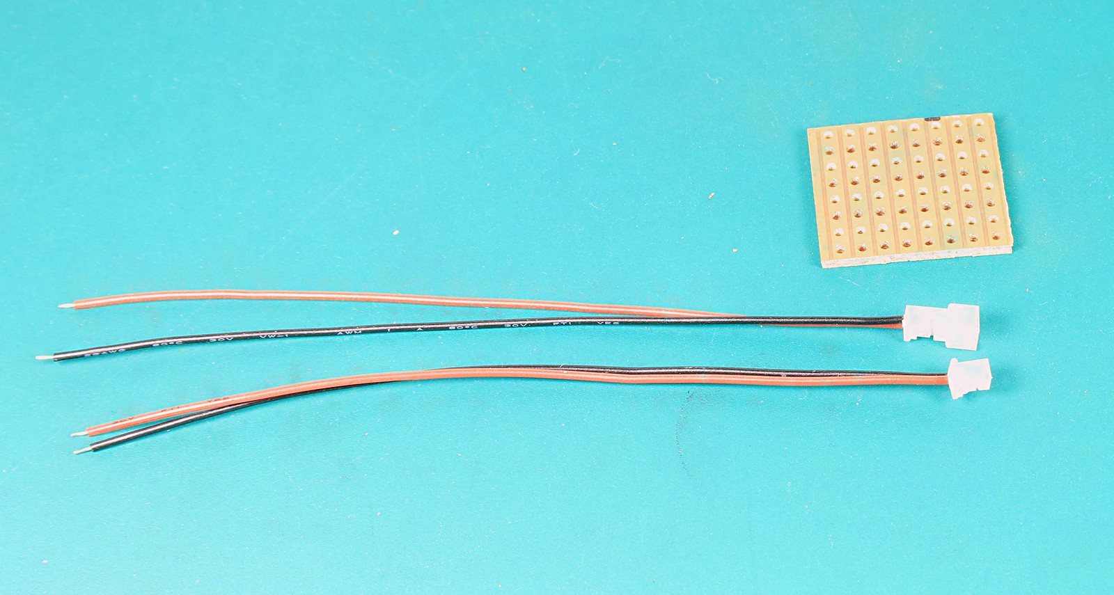
First I guesstimated the lengths of wire needed to reach from the plunger to the connections on a piece of Vero Board. These I soldered to the tags provided with the plungers

52218496154_4555e403ac_h.jpg


52218702565_fa46708cc5_h.jpg


Connection between the tender and loco is to be by a mini plug sold for PC's and bought via eBay some time ago.

One thing that makes life a little easier when dealing with the 12BA nuts on Slaters Plungers is a pair of flat 12BA spanners available from Eileen's Emporium

52217216887_6c70900620_h.jpg


52218702960_4959219dc1_h.jpg


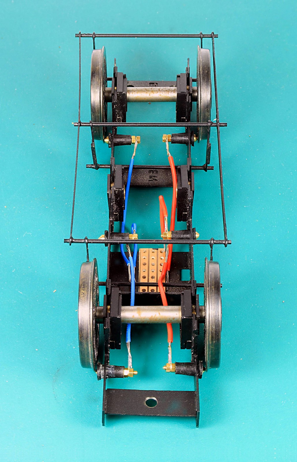
Here it is all wires connected to the plungers and ready to solder to the Vero Board

52217216152_61e87d8b93_h.jpg


Finally all wired up. - The observant amongst you will note that the size of the Vero board has changed in the last photo. I made a right pigs ear of soldering the first piece managing to bridge the gaps between the strips with solder so I did it again. Thankfully I hadn't got all the wires on before I cocked it up.
 

Richard Gawler

Western Thunderer
Rob this all looks so light and airy and spacious.

For those who have battled with these pickups (as I did):
  • It took me an embarrassingly long time to realise, you can slip the solder tag (with its wire attached) and the second nut onto the pickup and then pass the entire assembly through the hole into the frame into its final resting place. This is vastly easier than installing the pickup first and then trying to attach the tag and the second nut.
  • I add a short piece of heat shrink sleeving over the wire and tag to provide a mechanical support to the soldered connection. I do this from my experience at work not from model making.
  • The plunger housings do not connect with Araldite, so if they are a press fit into the frames this helps to secure the completed assembly.
I think it is sensible to use spanners not solder to lock up the two nuts, this will make future modifications a lot easier.
 

Rob Pulham

Western Thunderer
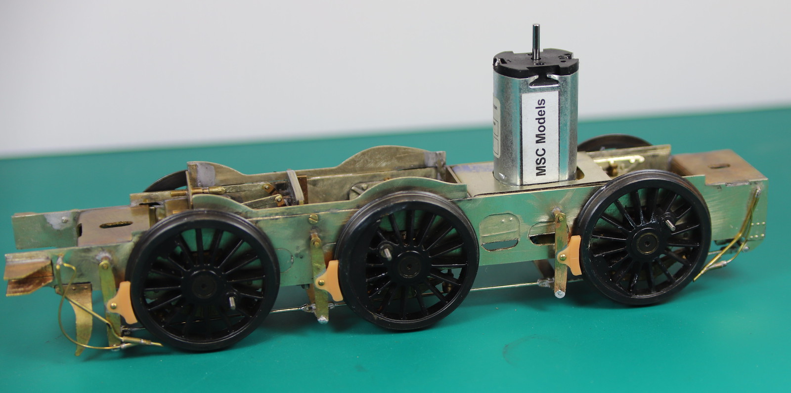
Not too much done on the J6 this week but it's almost there now.

I had a bit of a fright when I fitted the motor and I couldn't get the body on but thankfully I had just put it in the wrong way round.

What it did need is a motor mount/steady to stop it moving backwards and forwards inside the body. I cut a small piece of nickel sheet as a sliding fit between the frames and then cut out the mounting hole. I worked out where I needed to fold it and then decided to give the bending shear on the MiniFormit a try. I am pleased o say it bend it perfectly. Not being used to using it, to make bends. I didn't follow the bend through to a right angle. instead I finished it off in my hold and fold.

52232435715_7d41b3dab6_h.jpg


52231951326_08e876f745_h.jpg


I just need to solder it in now.
 

Rob Pulham

Western Thunderer
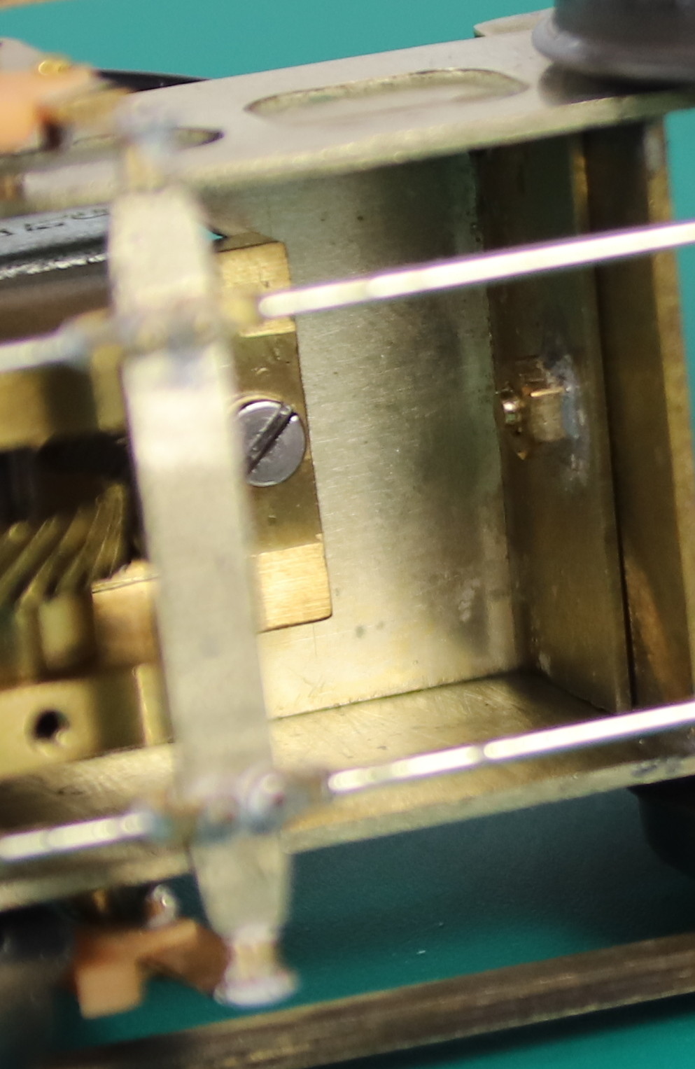
Contrary to my last post I decided to see if I could make the motor mount removable. It proved not too difficult to add a screw and retaining nut to the adjacent frame spacer.

52262375626_1ce842e3a4_h.jpg


52262858155_9b91d3e9a7_h.jpg


The motor mount also made a convenient place to mount a piece of Vero board which means that I can now remove both the motor and mount together without having to unsolder any wires which I count as an unexpected win.

The hole in the tender plate which supports the bottom end of the pivot pin was much bigger than the screw itself (8BA) and after fiddling around for about 10 minutes trying to get the screw to engage in the nut I decided to turn a small bush to centre it.

52262375116_72862e8ead_h.jpg


52261400907_3b365f1d44_b.jpg


52262386723_1a621d54b2_h.jpg


I am getting dangerously near to painting the chassis.
 
Top