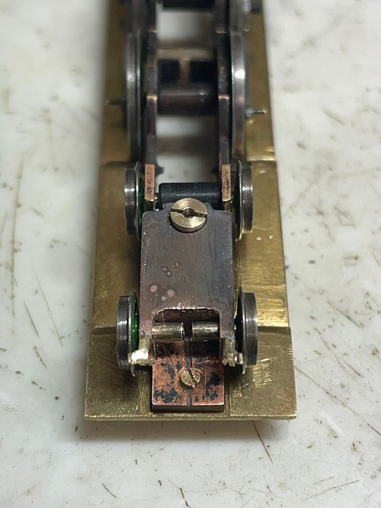
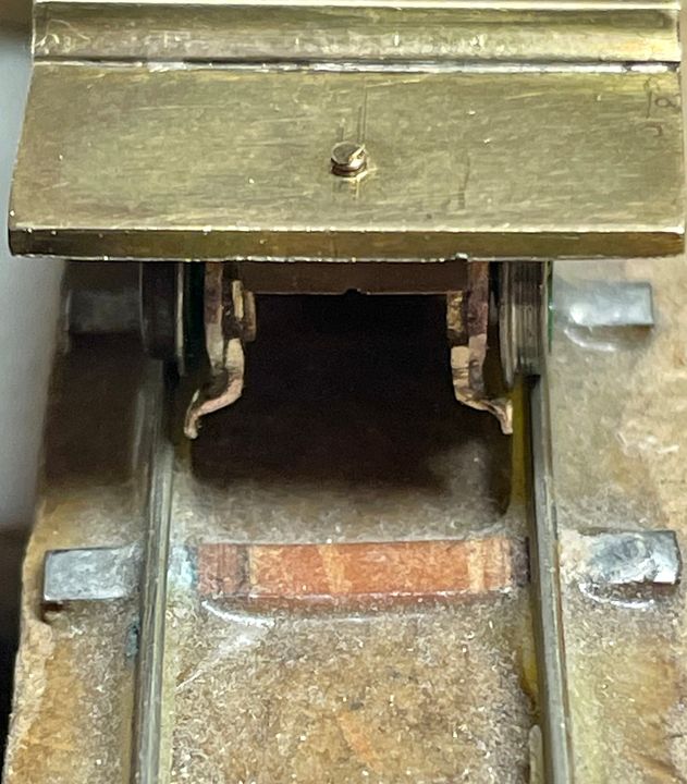
TFW’s workshop

Tim Watson

Western Thunderer
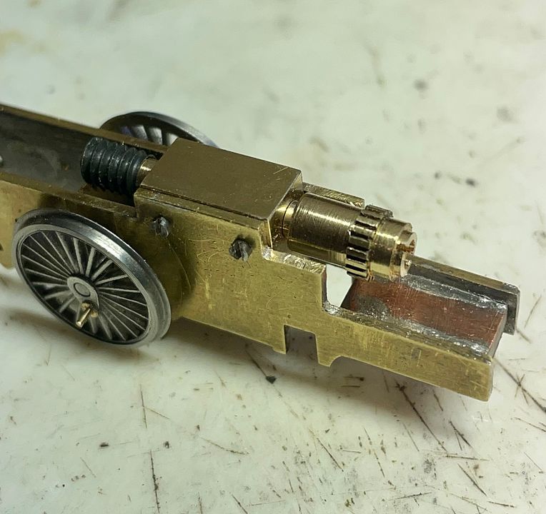
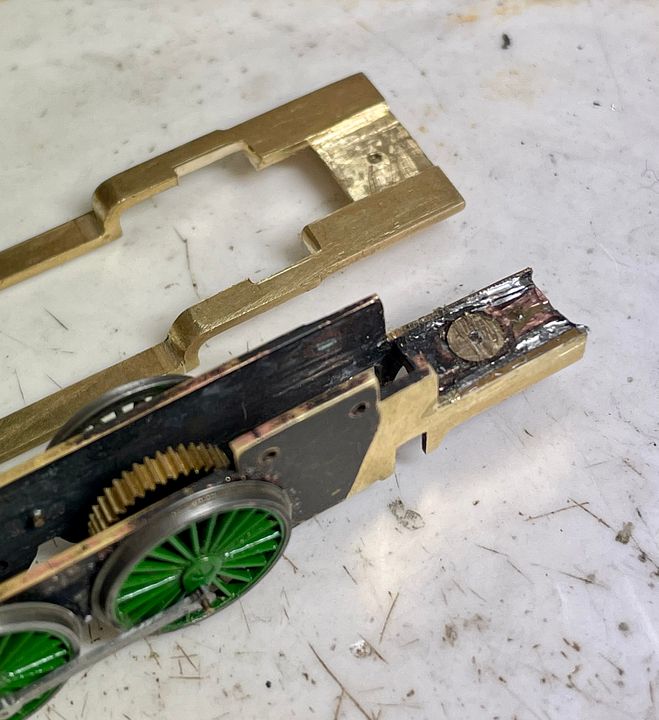
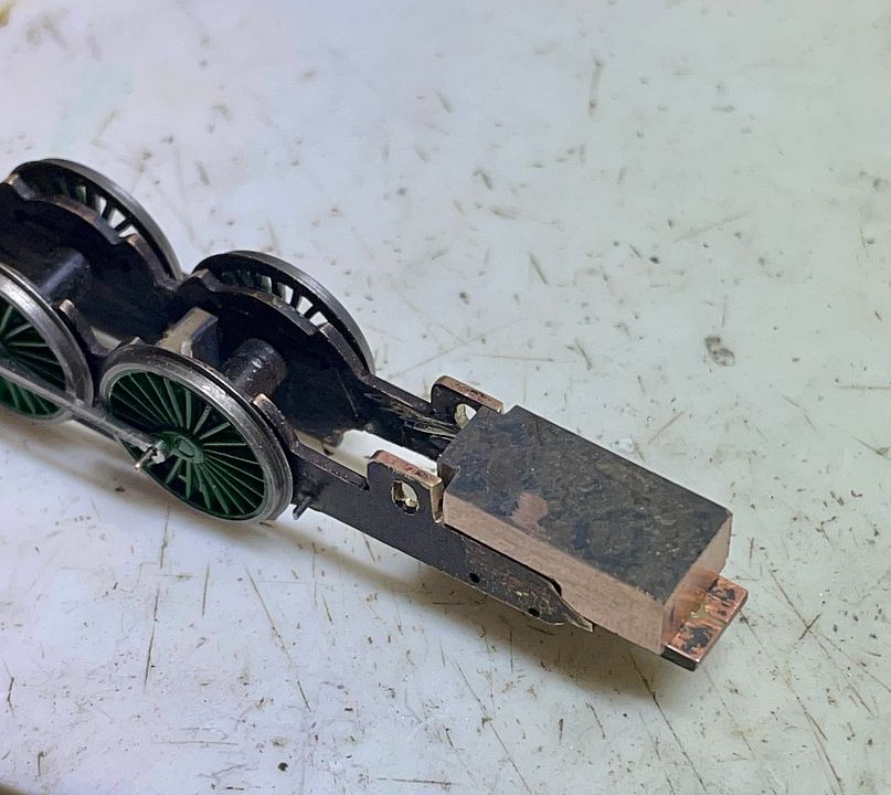
The gear head for the Raven NER 4-6-2 has been made from a 6x10x10mm block of brass. This was initially an interference fit between the frames to help determine the worm and worm-wheel mesh.

The frames and block were then drilled for 14BA to hold this position.
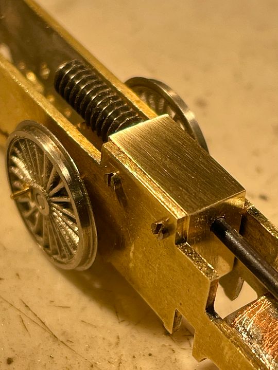
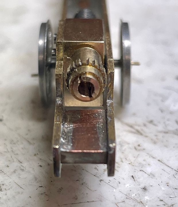
The gap next to the opposite frame is just visible behind the shaft. The wheels are not at the final back to back measurement; allowing easy adjustment at this stage. The worm is twice as long as it needs to be and will be trimmed and a thrust washer placed next to the bearing.

The non-bolted side was trimmed back on some sharp Vallorbe files to be clear of the opposite frame (for electrical isolation).
The edges of the block were lightly bevelled - it’s engineering, not clockmaking where the edges should be sharp enough to cut…

Tim
 

Tim Watson

Western Thunderer
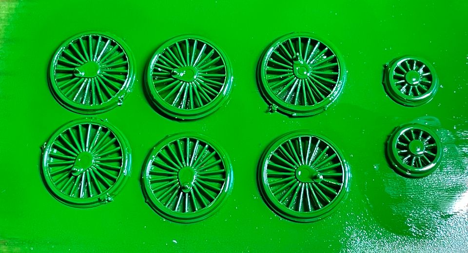
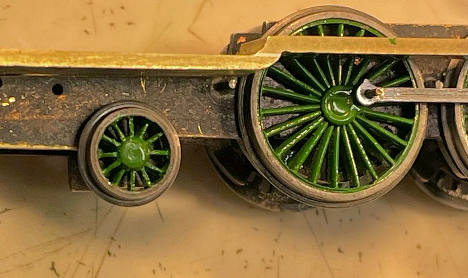
NER green is pretty bright!


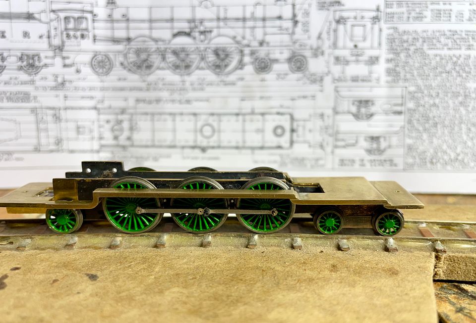
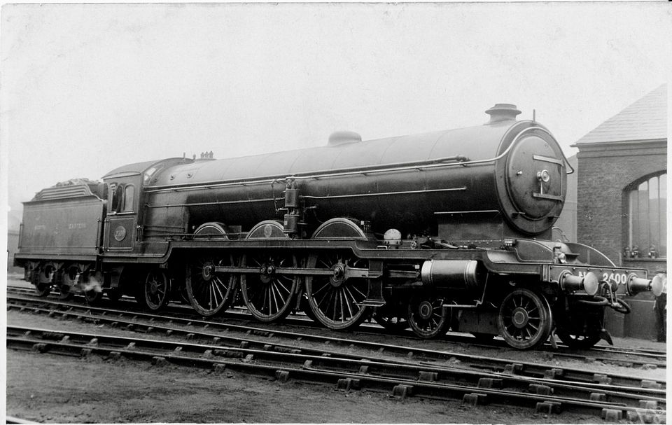
Rummaging through a tobacco tin, I very luckily found some 12 spoke 3’9” wheels that Denys Brownlee had roughed out 30+ years ago: these were correct for the very conspicuous trailing radial truck and just needed finish turning. The front bogie wheels will have to be hand made. The basic chassis should be running soon.

Tim
 

Tim Watson

Western Thunderer
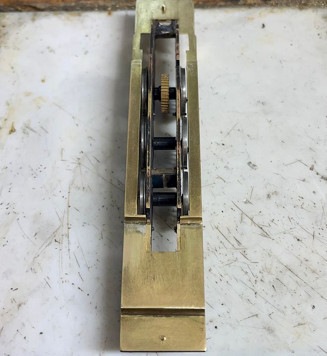
The gear head and loco universal joint were finished a few days ago; the worm shortened and thrust washers placed at each end.


The cut down teeth on the UJ cover is from an old eccentric Association gear. It makes it easier to turn the shaft by hand.


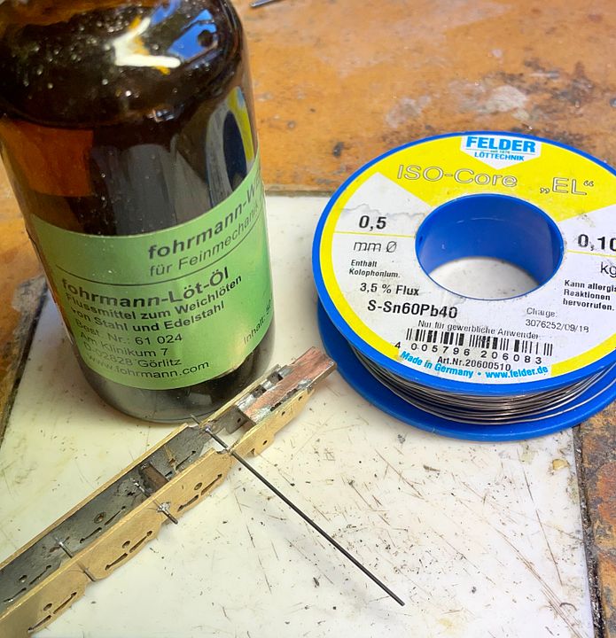
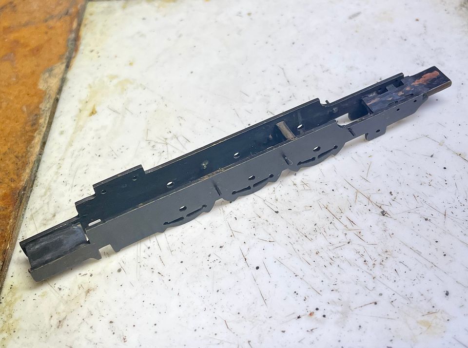
The brake hangers on the frames were made from pivot steel soldered through holes into place with a very effective solder and flux.

The flux is a very corrosive oil and so the chassis was degreased and then boiled in water for 5minutes.

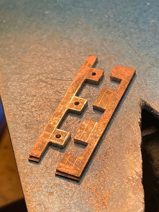
The next stage was to complete the frame spacer at the front end of the loco; the notches inside the frames are to take the nuts of the studs that will hold the cylinders in place.

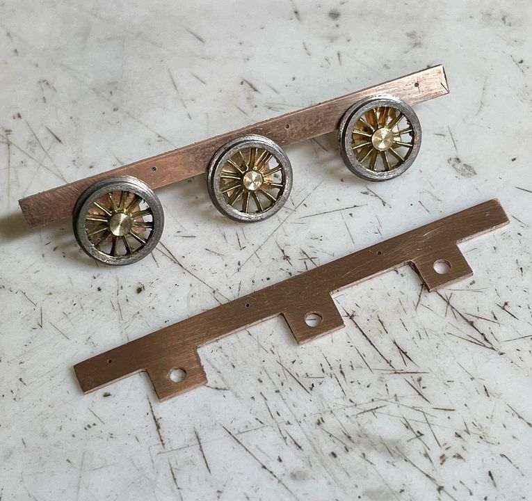
The frames were chemically blacked: much better than painting. The drive from the tender needed a chassis, so this was cut out of two layers of phosphor bronze strip sweated together.


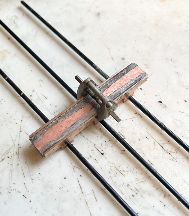
The frames were clamped up onto the PCB spacer, held in place by an orthodontic arch expander, and the siting rods (as usual) helped in alignment before soldering.


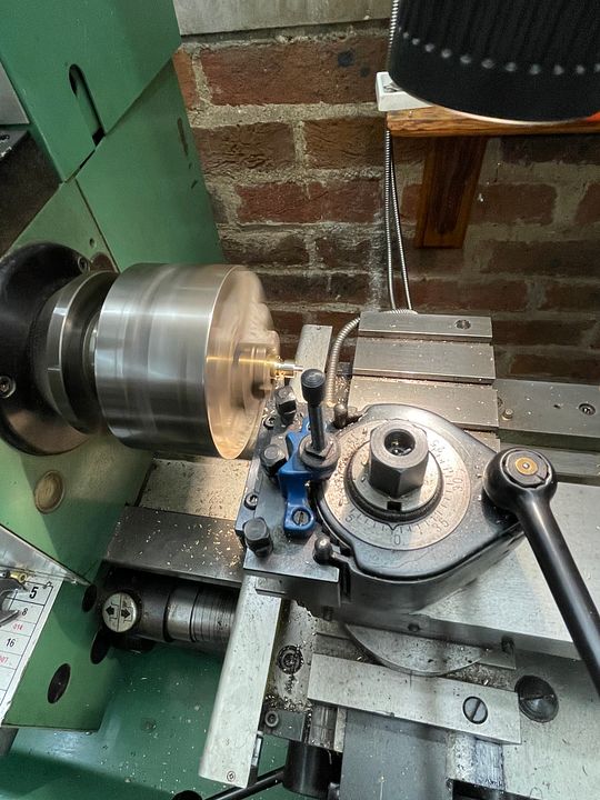
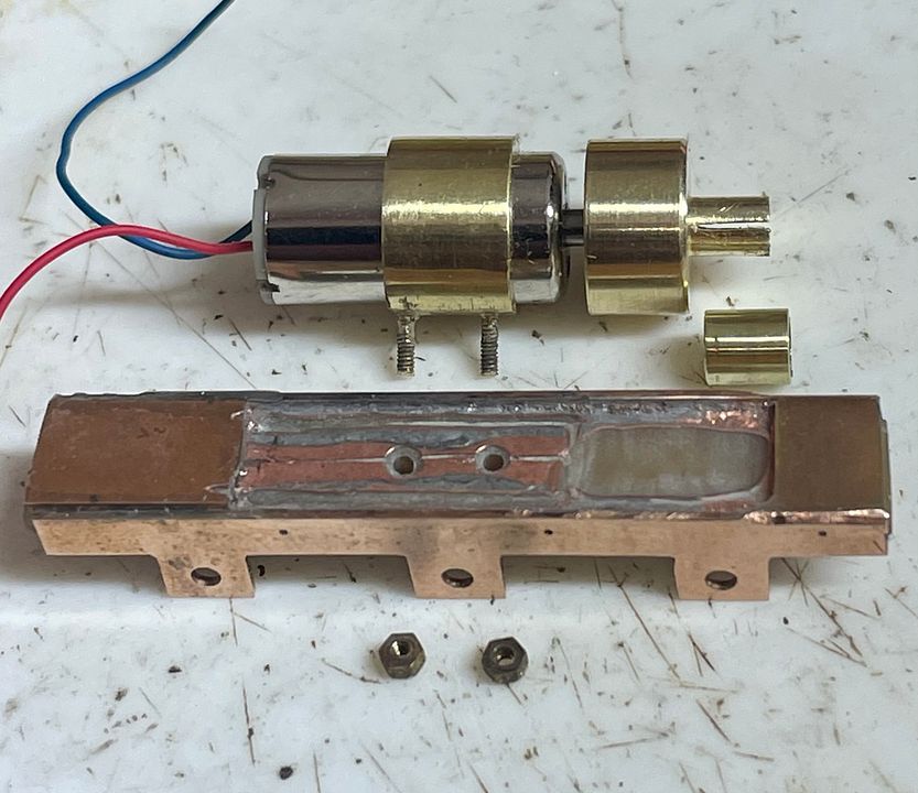
The Tram Fabrik motor obviously needed the other half of the UJ and so this was also incorporated into a flywheel. This was started on the big lathe in the garage: namely the main body, the smaller diameter UJ section and the 2mm diameter counter bore.


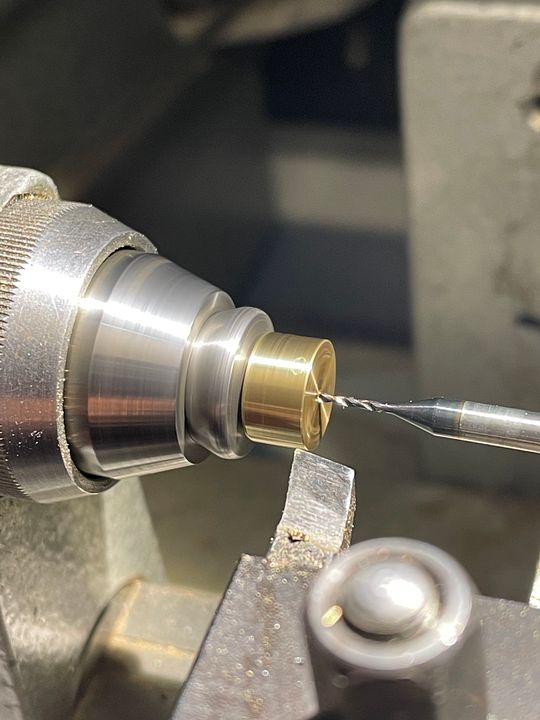
It was then taken into the garret workshop and finished off by drilling the shaft hole (0.9mm with a short section at 1.0mm) mounting the UJ section in a collet in the watchmakers lathe (it’s also much warmer upstairs)

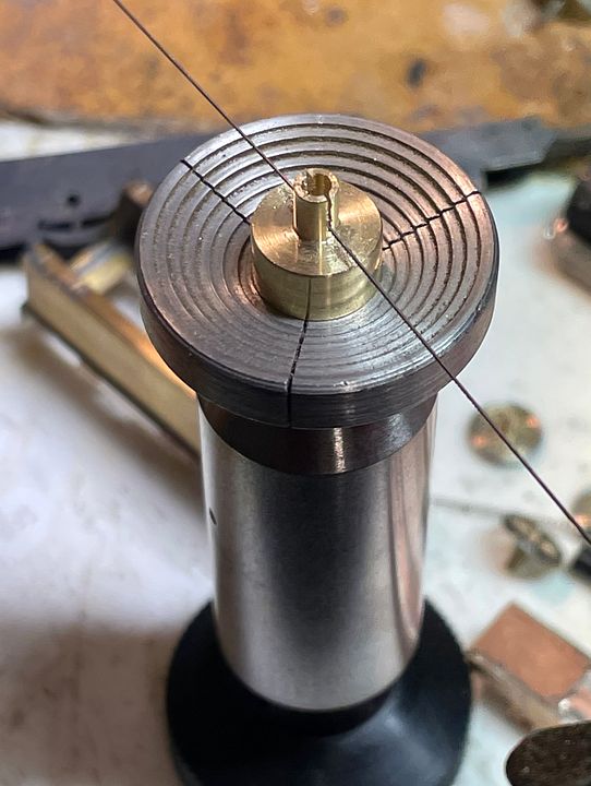
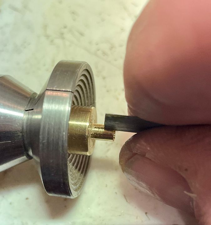
The hole was then taken up in size with a tapered broach until it just slipped onto the motor shaft to within a millimetre of the final position. The UJ slot was cut with a piercing saw and then finished with a slitting file, whilst holding it in a mandrel and a stepped chuck.


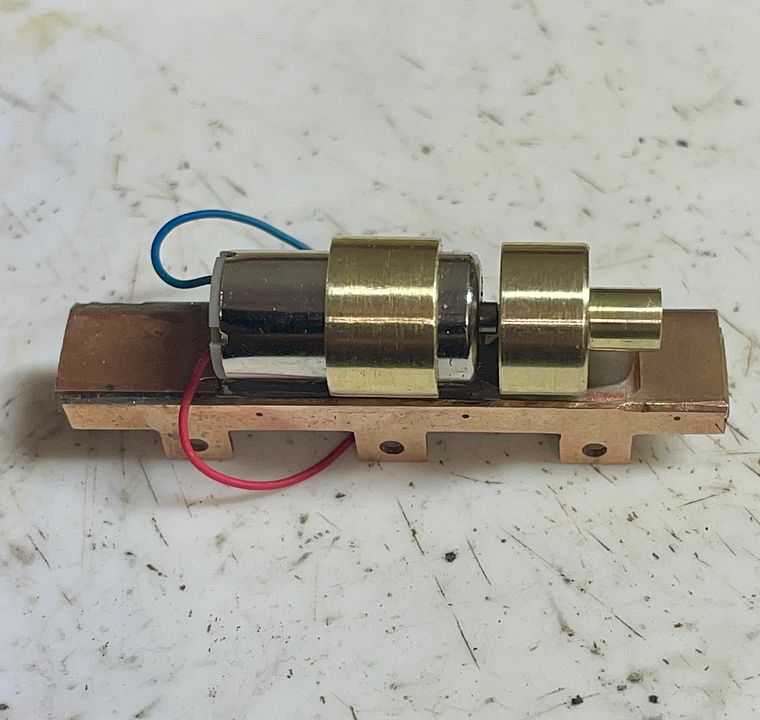
The motor itself is mounted in a brass collar with two 14BA studs silver soldered to it. These are then bolted through the PCB spacer.

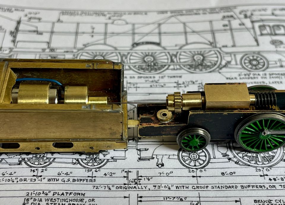
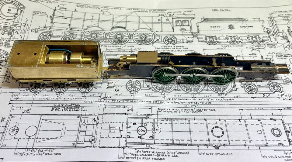
The flywheel was gently pushed home with some Loctite 601 on the shaft. The whole assembly easily fits into the tender: it could have had a bigger flywheel, but that would have sat quite a long way forwards and not too good as a side load on the front bearing.

The two PCB pads at each end of the tender frames are Araldited in place and slightly raised to keep the body from shorting out the split chassis.
Anyone who has got this far deserves a medal!

Tim
 
Last edited:

Tim Watson
Western Thunderer
I hoped I might get the Raven 4-6-2 class running before Christmas and I have!
iPhones have a special microphone for picking up 2mm loco noise. It is currently running dry, which doesn’t help too much either.
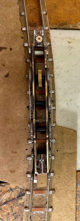
The drive arrangement is, as always, through a 10thou spring steel shaft with loops each end.

It’s going to be an interesting engine to get round corners.

All in all, I’m relieved it runs.

Merry Christmas everyone!
Tim
 
Last edited:

Tim Watson

Western Thunderer
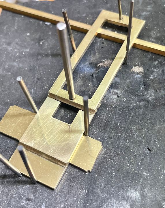
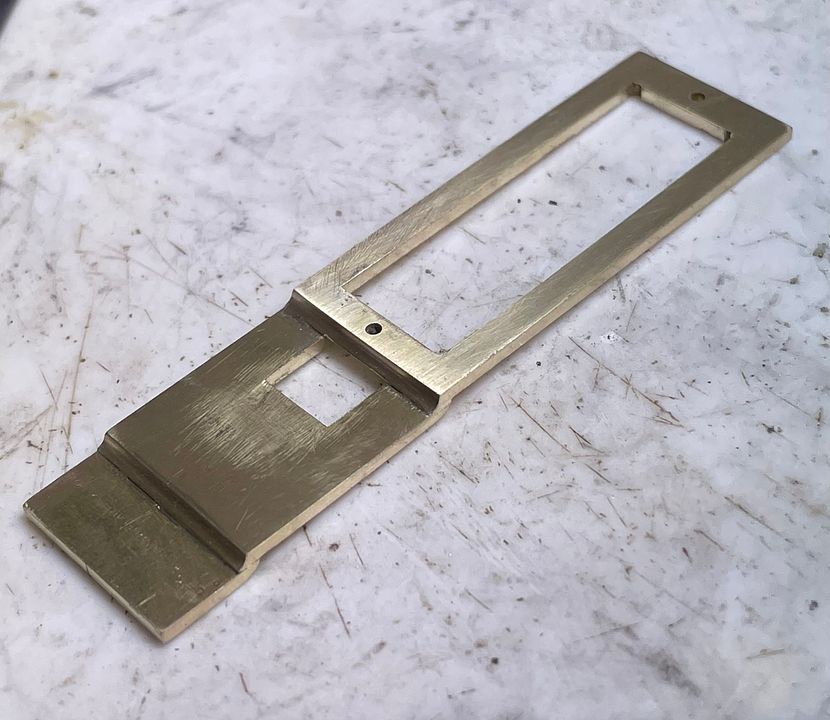
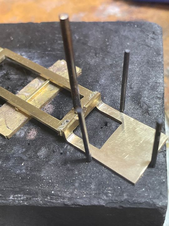
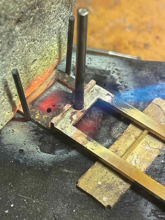
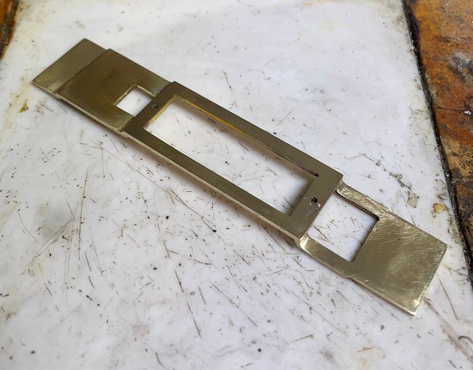
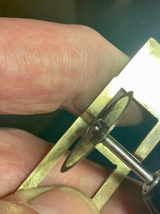
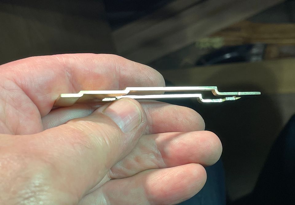
Work on the wavy, cascading, front running plate for the NER 4-6-2 class has been started. It is quite a challenge to keep such structures level and so the foundations are made from three pieces of 1.4mm thick brass silver soldered together: this will represent the valence on the edge of the running plate. Cutting in the concave form at the front of the running plate was achieved using an old steel finishing bur (they used to be used in dentistry) the surface irregularities were then tidied up with a fine round file.


The components were set up a charcoal block ready for heating up, held in place with pins from broken drills. The solder paste can be seen in the middle joint - the other had been made previously. Powder borax flux is also added. The flame I use is a little gas torch - similar to the ones used to burn crème brûlées.


Removed from the block and cleaned up. The rebate at the front of the concave forms will take the 5thou nickel silver running plate tops: these will have the fine details on them and, of course, the driving wheel splashers.


The smoke box saddle will be bolted through at the front, not surprisingly, It will be a solid lump of brass. In fact, I suspect this engine will weigh in heavier than Mons Meg.


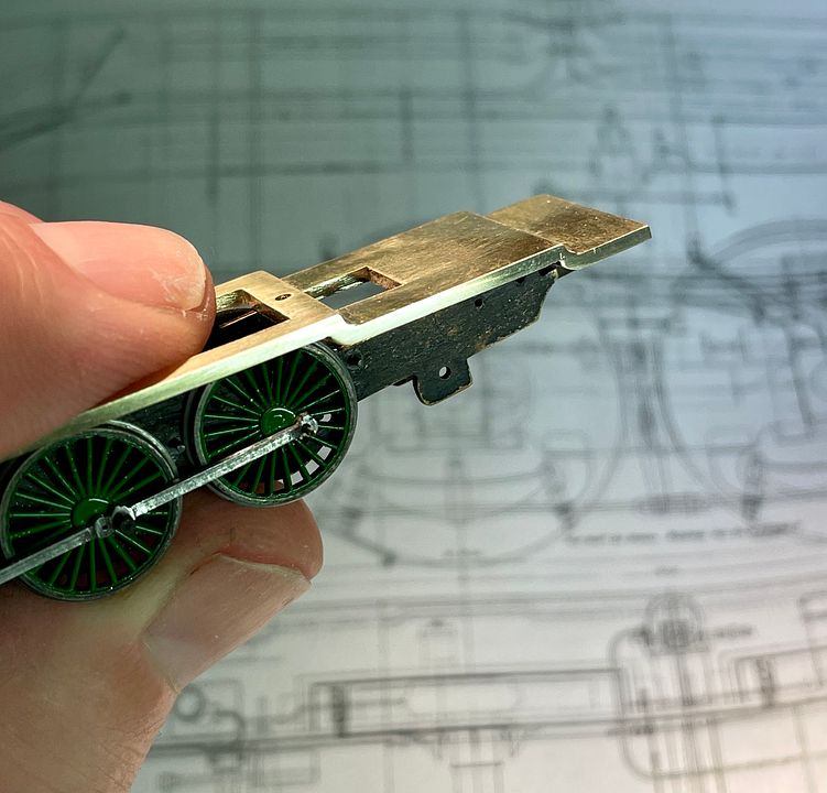
Finishing with a bit of an arty shot with the running plate approximately held in place. There are sacrificial stiffening spacers that will be cut away once the back end is complete.

Tim
 

Tim Watson

Western Thunderer
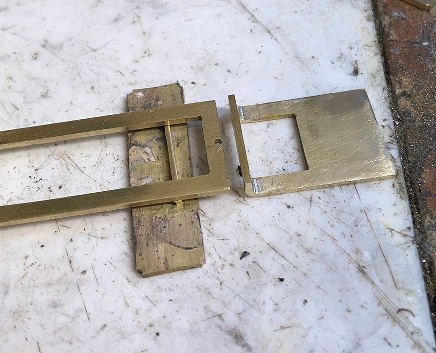
Sorry to be a bit repetitive but after a productive session today the running plate core is now complete for the Skittle Alley: now becoming an exceedingly long locomotive. The rear section was bent up and butted up to the middle. The hole in the stretcher is to take a locating pin when silver soldering.

As before, the components were set up on the charcoal block and held in place with pins from drill shanks.

In this photo the solder has just flashed: the flame and residual hot charcoal are visible.

After cleaning up, but before removing the stretchers.

These were removed with a fine diamond disc.

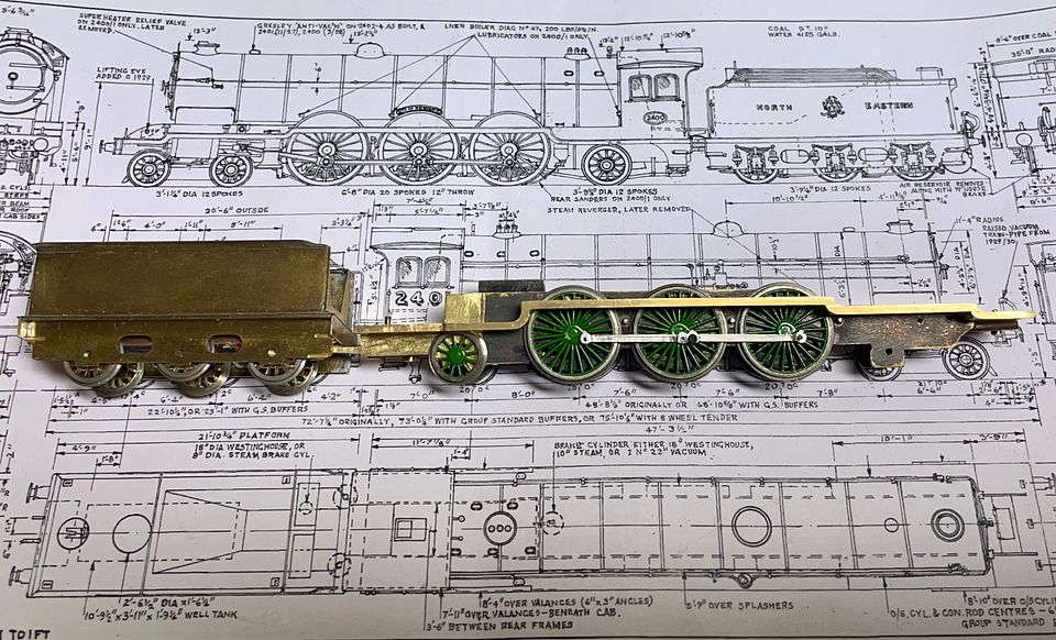
Now set up on the engine.

Whilst this part of the engine represents a good deal of work, it does give a solid foundation for the loco body. If it were etched, a sacrificial assembly jig would help in construction (as with Valour). If it were 3DP it would be simple to make. However, neither would be as strong as this solid brass assembly.

The valence will be reduced in height by 0.2mm - when I have fresh pair of eyes.

Tim
 
Last edited:

Tim Watson

Western Thunderer
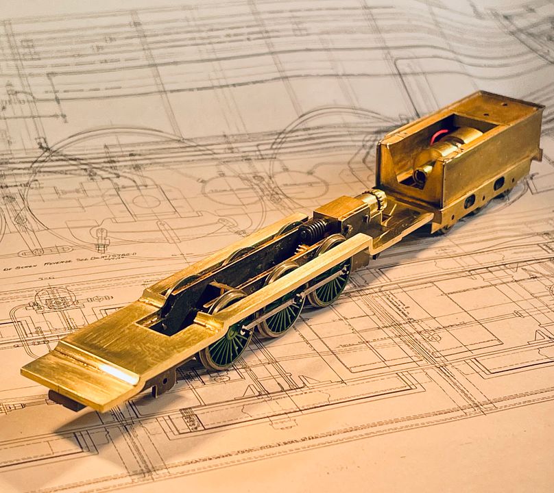
After a great deal of fettling and fitting the running plate core is now fixed solidly to the chassis for the Raven NER 4-6-2 class. It had to be lowered quite a distance, compared to the starting position, and was also reduced in thickness by 0.25mm.

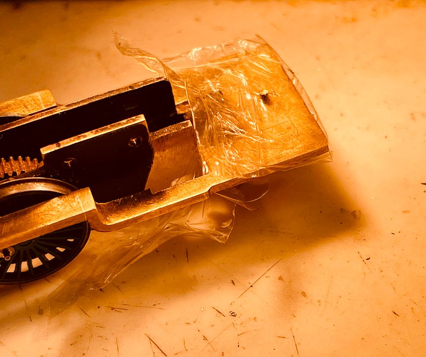
There are two 14BA fixings, one at the front, one at the rear. The body is live to one side of the engine. It was important that the rear fixing could give stability and so a thin strip of very thin PCB was soldered to the top of the ‘insulated’ frame where the stretcher sat. The fixing bolt was then well greased up (as well as the associated tapped hole) and some cling film wrapped around the body section. Slow setting epoxy resin was then placed on top of the spacer, the body positioned and the bolt tightened up through the epoxy resin; squeezing it between the cling film and the chassis - effectively making an insulated bed for the body to fit onto. The whole assembly was cooked under a couple of hot spot lights for an hour.

The body was removed from the chassis well before the resin had completely cured and any excess trimmed way with a scalpel.

The clear resin doesn’t show the seating very well, but it does give a nice solid fixing for the rear bolt. The wheel clearances are obviously fairly tight and so accurate fixing for the body is essential, if scale widths are to be maintained.


I have worked out how the bodywork will be made: mainly as subassemblies, to ease the painting in NER livery, which was slightly more complex than the LNER style. That being so the smokebox saddle and boiler could be next or maybe the radial truck at the back. Just need to make my mind up… I must say how enjoyable it is to be making an engine from scratch again. I find the problem solving the best bit.

Tim
 
Last edited:

Tim Watson

Western Thunderer
Well, I changed my mind. The front bogie wheels had been giving me pause for thought as they are of typical NER pattern 12 spoke at 3’ diameter.
(Photo courtesy Blandford 1969 from RMWeb)
The Association only makes a ten spoke wheel at that diameter.

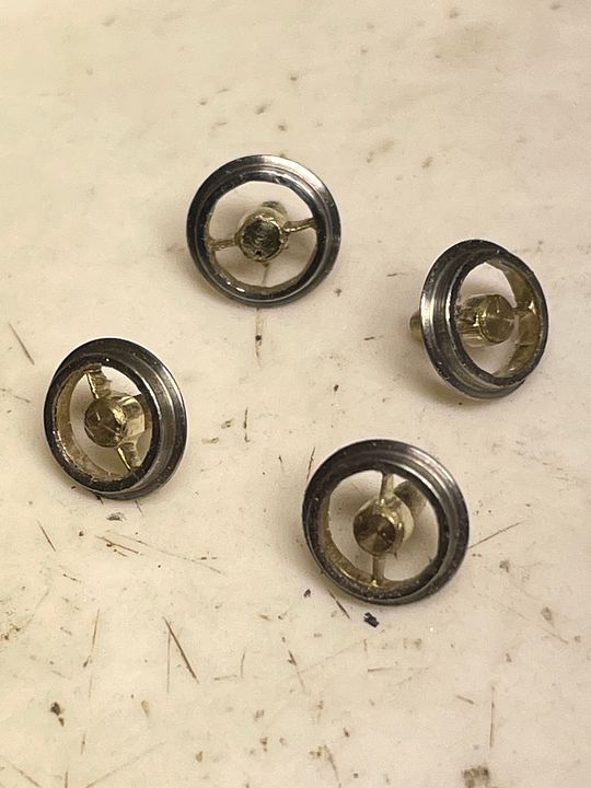
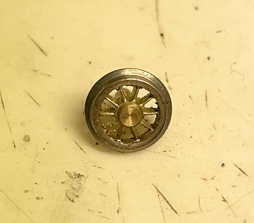
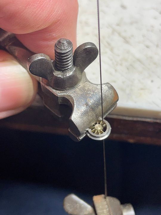
There is a school of thought that says you never see the spokes when the wheels are going round. That is perfectly true, of course, but it somewhat irritates me to see the wrong wheels under an engine, especially when they are so characteristic of a particular railway. I have made wheels in the past and was resigned to turning up some steel blanks for the purpose. It then occurred to me that the ten spoke wheel could easily by converted, so eight of the spokes were cut out with a piercing saw: one cut near the hub, the other at the perimeter.

The cutting scars were filed away and the hub reduced in size as well as the rim: I wanted the spokes to be as long as possible - many model wheels are too heavy in these areas.

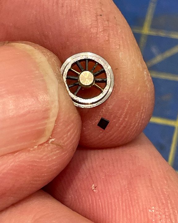
The ten replacement spokes were made from 10thou black styrene cut into a small rectangle that was very slightly trapezoidal in shape. This gives just a slight friction fit between the hub and rim. Setting up these spokes was easy, they were in essence a clock face. The penultimate styrene spoke can be seen ready for placement on my finger tip.

Once the spokes were in position a minute drop of very low viscosity cyanoacrylate adhesive was flooded into the end of the spokes, using a fine pin. Super glue can be slowed down in ‘going off’ by placing a drop onto a plastic bag to pick up from. Once set, the spokes were trimmed to shape using a scalpel and an ultra sharp chisel.

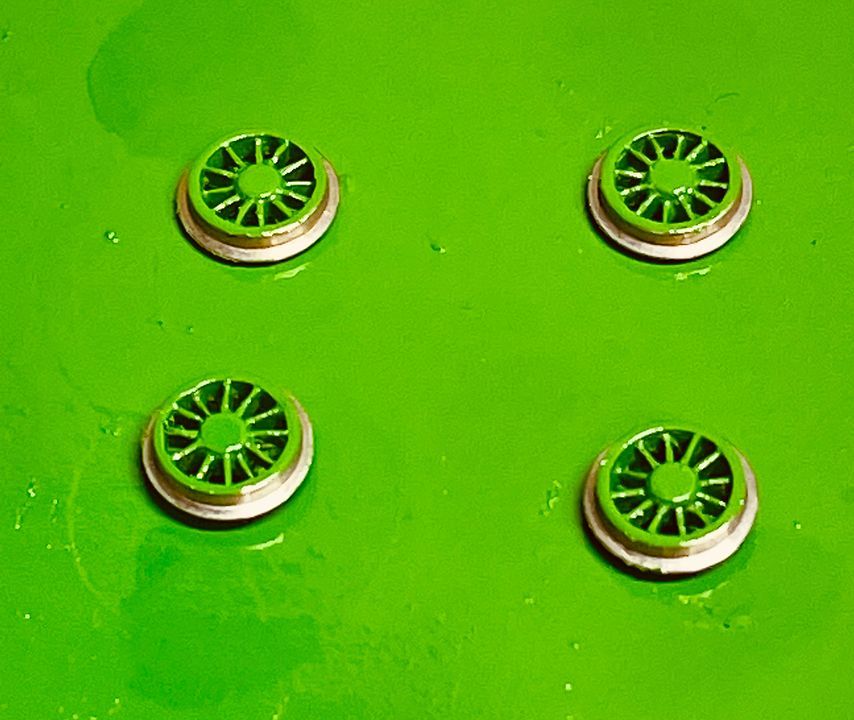
The wheels were then given a coat of NER green: they are looking a bit vulgar in this photo. They will hopefully look better when the rims and hub are black.


Worth all the effort? A few hours work - what do you think?

Tim
 
Last edited:

Tim Watson

Western Thunderer
Work has continued on the front bogie / pony truck for the long engine. The rear bogie wheels have a vertical slot to move up and down. The front pony truck started out as a lump of copper tungsten (heavy alloy - upside down in this photo).

The 12BA rear pivot and axle hole were drilled in the roughed-out block so that the whole engine could be tried out on my test track minimum radius, before committing too much effort.

The test track was actually a section lifted from Chiltern Green forty years ago and is substantially below the 600mm radius on CF. It all fits on the curve, but I dare say there will be some squealing - especially with a solid 1/2” diameter brass boiler sitting over the top.

There is a lot of work to finish off the ‘pony’ truck, but at least it now looks a bit more joined up at the front.

Tim
 
Last edited:

Tim Watson

Western Thunderer
Today’s saga sees the pony block trimmed into a functional relationship with the chassis after a good deal of milling and filing. The frames at the front of the bogie are open, with the springs, front axle boxes and associated keeps visible.

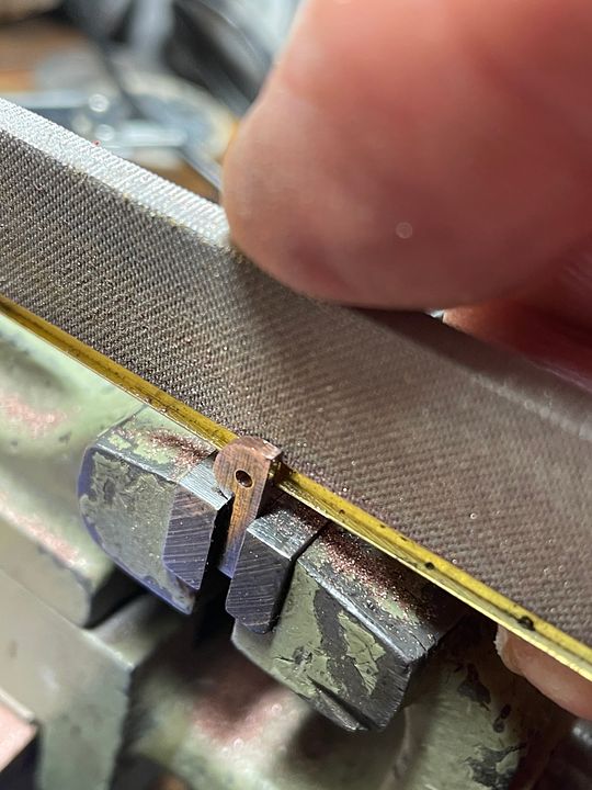
In order to make the frames thinner at the front from the inside I used a sharp file, but had a piece of brass underneath to support it and act as a runner so producing a neat rebate, by filing on the side.

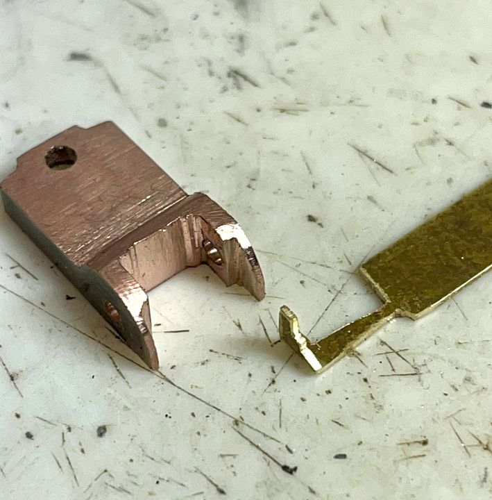
The end result then gives space for the front guard irons. These were made from brass, as copper tungsten is a bit brittle in thin section. It’s always easier to make small pieces with a handle and then chop it off.

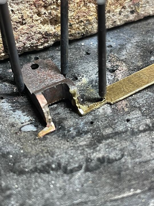
Copper tungsten does not soft solder but will take silver solder, as can be seen with the components pinned down on the charcoal block.

The ‘pony’ set up can be seen with the pivot comprising a recessed 12BA T nut. The head will be flush with the bottom of the bogie, once ride heights etc. have been finalised.

The guard irons are very small, but quite a critical visual part of the bogie. The spring detail is probably just sufficient to give the impression of its function.


Tim
 
Top