You are using an out of date browser. It may not display this or other websites correctly.
You should upgrade or use an alternative browser.
You should upgrade or use an alternative browser.
TFW’s workshop
- Thread starter Tim Watson
- Start date
Tim Watson
Western Thunderer
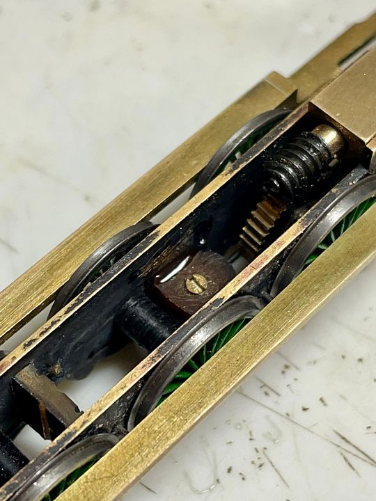
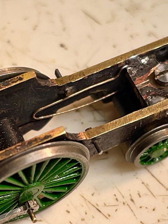
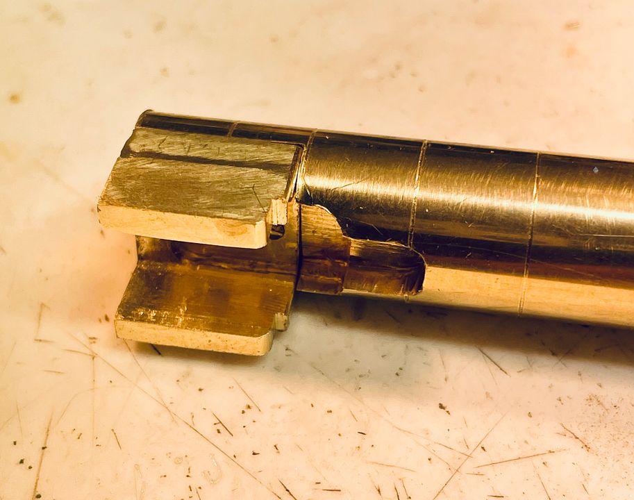
A block of copper tungsten does present some challenges electrically for split frame pick up. This was resolved by cutting a slot for 7/8s of the length of the block. The slot was then filled with 24hr epoxy resin, with styrene ‘shuttering’ temporarily glued in place to constrain the resin. Once this had cured the remaining 1/8 was cut through and this section filled in with epoxy resin. It’s a technique I used for Mons Meg’s carrying wheel truckd, but the idea is based on the old fashioned way to make Hornby Dublo three rail wheels insulated: cut alternate spokes - fill with epoxy - then do the same to the remaining spokes.
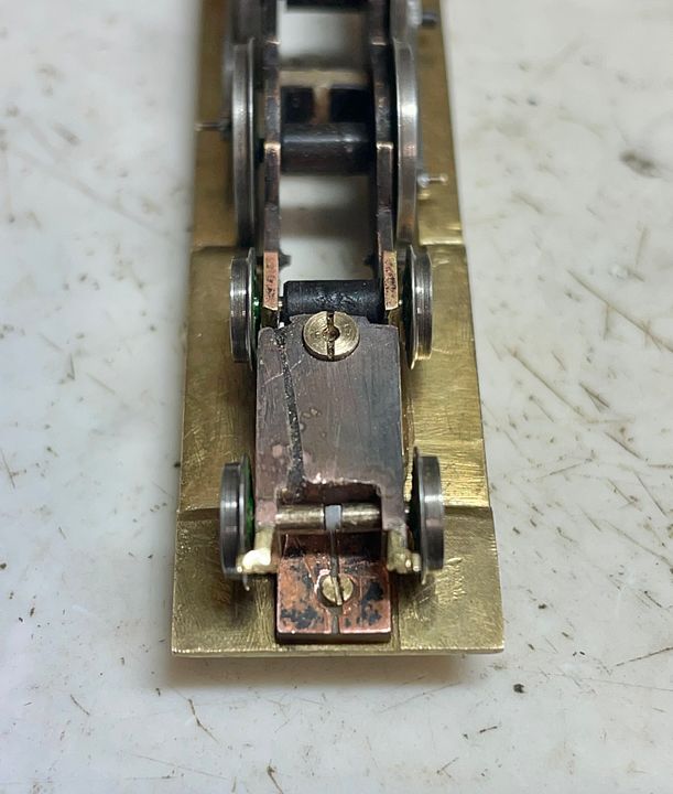
The front axle does not have an external muff (as usual with 2mm scale wheels) but an internal 1.1mm diameter glass-fibre-reinforced epoxy resin rod. The half stub-axles were drilled on the lathe to accommodate the internal rod (before my escapades with the styrene spoke replenishment). The rod will eventually be fixed with more epoxy resin, set to the correct back to back. The advantage is a scale diameter axle visible from the front.
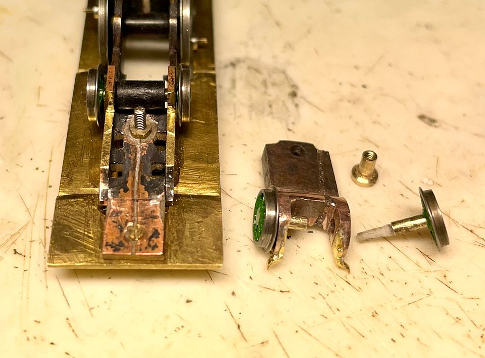
The T nut can be seen in the background; this helps to control the ride height of the ‘bogie’ frames. I may use the 12BA bolt head (not visible) to locate a recurved spring to act on the centre of the rear bogie wheel muff to help its tracking.
Tim

The front axle does not have an external muff (as usual with 2mm scale wheels) but an internal 1.1mm diameter glass-fibre-reinforced epoxy resin rod. The half stub-axles were drilled on the lathe to accommodate the internal rod (before my escapades with the styrene spoke replenishment). The rod will eventually be fixed with more epoxy resin, set to the correct back to back. The advantage is a scale diameter axle visible from the front.
The T nut can be seen in the background; this helps to control the ride height of the ‘bogie’ frames. I may use the 12BA bolt head (not visible) to locate a recurved spring to act on the centre of the rear bogie wheel muff to help its tracking.
Tim
Last edited:
Tim Watson
Western Thunderer
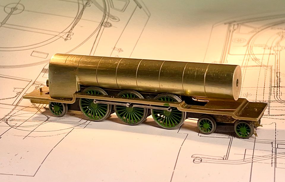
The Raven NER 4-6-2 class has now run as a 4-6-2, albeit with the radial trailing wheels bouncing along for the ride. They will need a proper truck to control them. I am pleased with the front bogie: it works quite well, even without any springing.
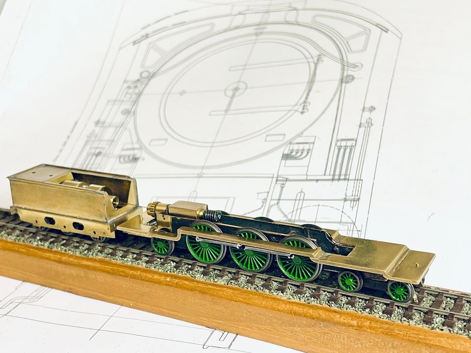
As ever, the phone picks up the noise of the mechanism rather well. I have now sourced some 1/2” brass for the boiler; 3” of that should work wonders for adhesion.
Despite what some people say about them, I think that this engine will look rather elegant when complete.
Tim

As ever, the phone picks up the noise of the mechanism rather well. I have now sourced some 1/2” brass for the boiler; 3” of that should work wonders for adhesion.
Despite what some people say about them, I think that this engine will look rather elegant when complete.
Tim
adrian
Flying Squad
I think I know what you mean - maybe not "elegant" but I do think they have a certain "brutalist" beauty to them.Despite what some people say about them, I think that this engine will look rather elegant when complete.
Tim Watson
Western Thunderer
The last few days have seen the radial rear truck made on the NER 4-6-2 class. Looking at the works drawings, the virtual pivot point for this is just behind the middle axle, so this is where I located it, as the engine would not have a true radial-truck slide-way arrangement.
The main components consist of the ash pan which acts as the bearing block for the back axle. The muff for the axle is 2.5mm diameter, and tapered at each end so that it can slide through the horn ways in the frames on an arc of movement. The muff is full wheel back-to-back width to give it plenty of grip on the stub axles. The front pivot is attached to the ash pan block using two, 0.6mm diameter, steel rods held in appropriate holes drilled just above the damper opening, with equivalent holes on the front pivot block.

The two rods allowed the radial arm(s) to pass either side of the gear wheel and are relatively stiff. It also allowed the pivot point to have a fine adjustment for radial length and then being soldered in place.
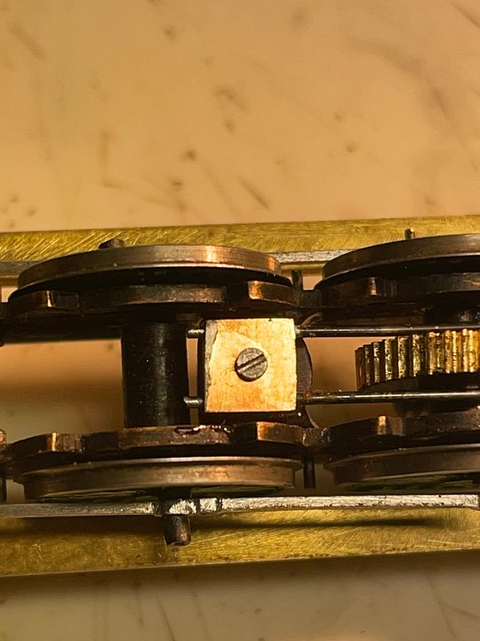
The mounting for the pivot bolt is a piece of high density Tufnol made as a tight fit in the frames and then secured with 24hr epoxy resin. The insulating block is tapped 14BA and there is a bolt screwed in from the top (visible in this photo) that acts as a stop for the actual pivot bolt which approaches from the underside.
The end result is a radial action which maximises the movement of the wheels, but in a well controlled manner, giving a smooth transition through curves.
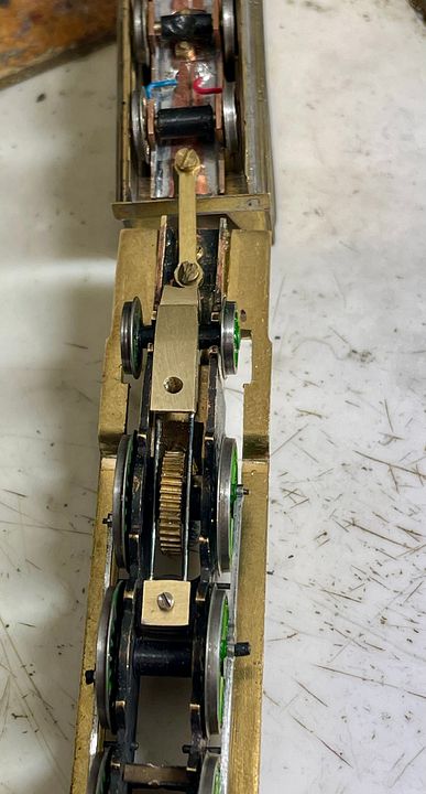
The hole in the bottom of the ash pan is not to improve draft but to allow access to the lubrication point in the gear head.
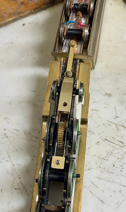
Having GA drawings is very useful when working out how to make a loco and I find it fascinating working out where everything goes.
Tim
The main components consist of the ash pan which acts as the bearing block for the back axle. The muff for the axle is 2.5mm diameter, and tapered at each end so that it can slide through the horn ways in the frames on an arc of movement. The muff is full wheel back-to-back width to give it plenty of grip on the stub axles. The front pivot is attached to the ash pan block using two, 0.6mm diameter, steel rods held in appropriate holes drilled just above the damper opening, with equivalent holes on the front pivot block.
The two rods allowed the radial arm(s) to pass either side of the gear wheel and are relatively stiff. It also allowed the pivot point to have a fine adjustment for radial length and then being soldered in place.
The mounting for the pivot bolt is a piece of high density Tufnol made as a tight fit in the frames and then secured with 24hr epoxy resin. The insulating block is tapped 14BA and there is a bolt screwed in from the top (visible in this photo) that acts as a stop for the actual pivot bolt which approaches from the underside.
The end result is a radial action which maximises the movement of the wheels, but in a well controlled manner, giving a smooth transition through curves.
The hole in the bottom of the ash pan is not to improve draft but to allow access to the lubrication point in the gear head.
Having GA drawings is very useful when working out how to make a loco and I find it fascinating working out where everything goes.
Tim
michael mott
Western Thunderer
Tim this is micro engineering akin to watchmaking.
Michael
Michael
Tim Watson
Western Thunderer
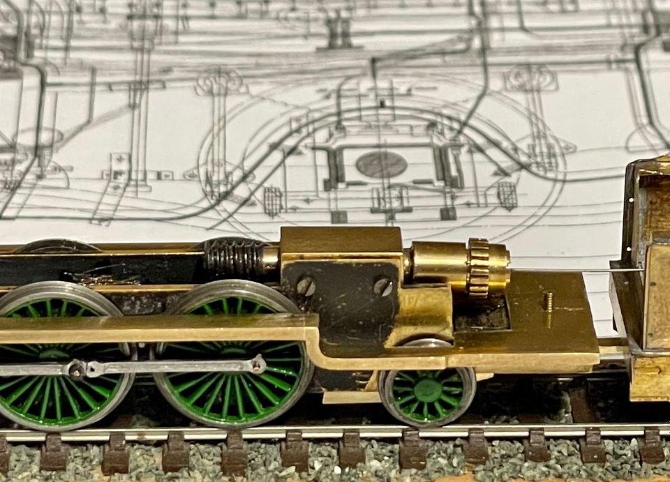
The main mechanical components of the NER 4-6-2 class are now complete. The final tweak was to add a couple of re-curved 33swg phosphor bronze springs on the rear axle of the bogie. The wires are held in place with solder, but are located in holes drilled in the frames.
These springs have stabilised the front end by working not only as a downward force on the axle but also damping side play from acting on the sides of the central muff. They will also give excellent current collection. Considering the great length of wheelbase of this engine it rides steadily through the reverse curves at slow speed without binding.
Tim
Last edited:
Tim Watson
Western Thunderer
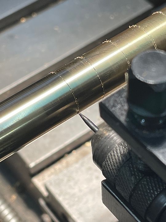
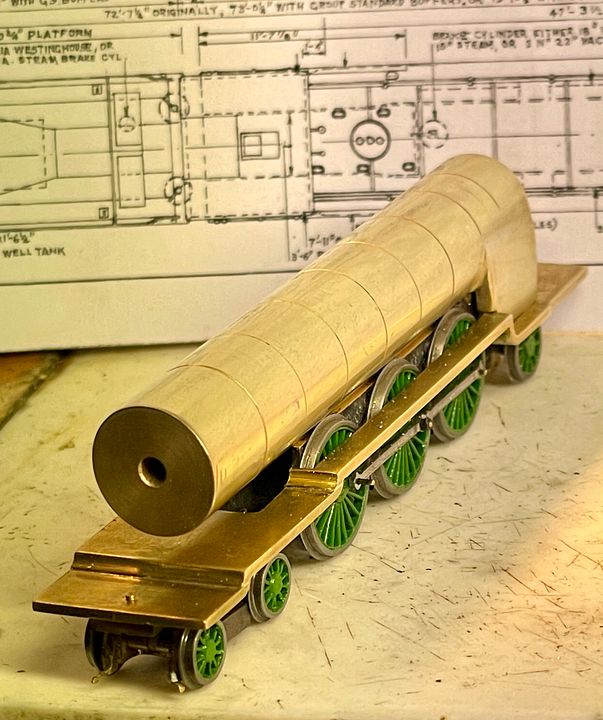
This is what you call a boiler!
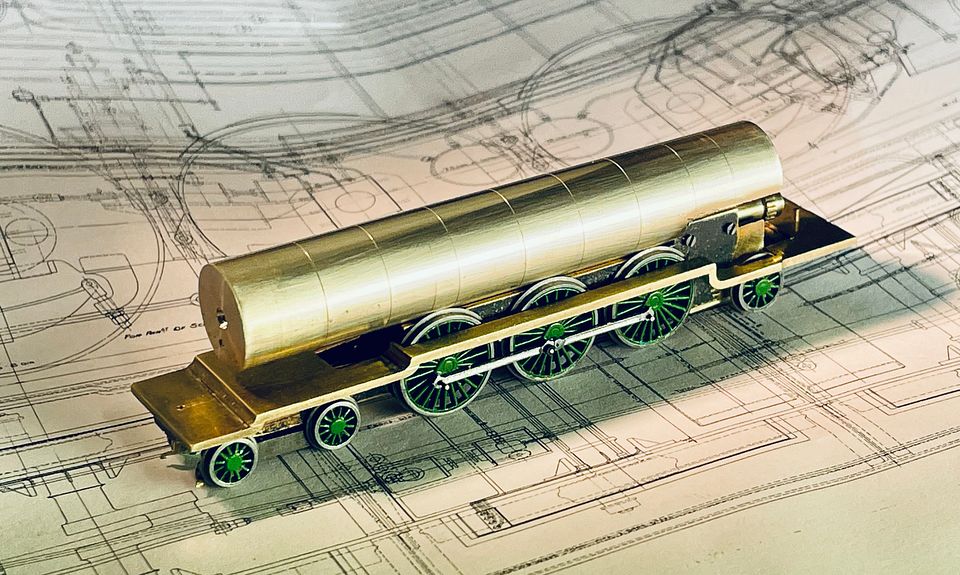
The boiler band positions were marked on the boiler using a gramophone needle held in the lathe (turning the chuck over by hand), moving to each position by dead reckoning (a digital readout helped). These witness marks make it much easier to position the lining transfers/boiler bands.
The engine currently weighs in at 105g. When the firebox, smoke box saddle and cylinders are added it will probably get nearer to the weight of Mons Meg (120g).
Tim
The boiler band positions were marked on the boiler using a gramophone needle held in the lathe (turning the chuck over by hand), moving to each position by dead reckoning (a digital readout helped). These witness marks make it much easier to position the lining transfers/boiler bands.

The engine currently weighs in at 105g. When the firebox, smoke box saddle and cylinders are added it will probably get nearer to the weight of Mons Meg (120g).
Tim
Tim Watson
Western Thunderer
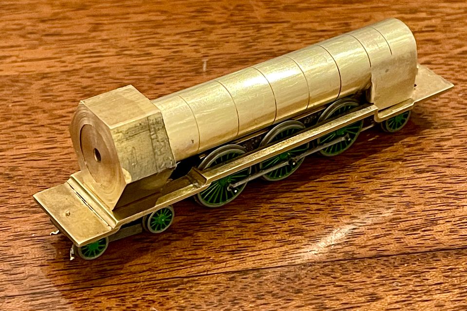
Some days you make a silly mistake which, by trying to fix your way out of it, wastes an inordinate amount of time. On the boiler for the long engine I milled away 1.5mm too much in the throat plate region of the firebox. I thought this could be remedied by soldering-in a packing piece. I did this but it was all looking a bit too scruffy, so I made a new boiler; which is what I should have done in the first place.
The new boiler was shaped correctly this time and the separate firebox sides and top milled from a lump of brass to bolt to the rebate in the boiler.
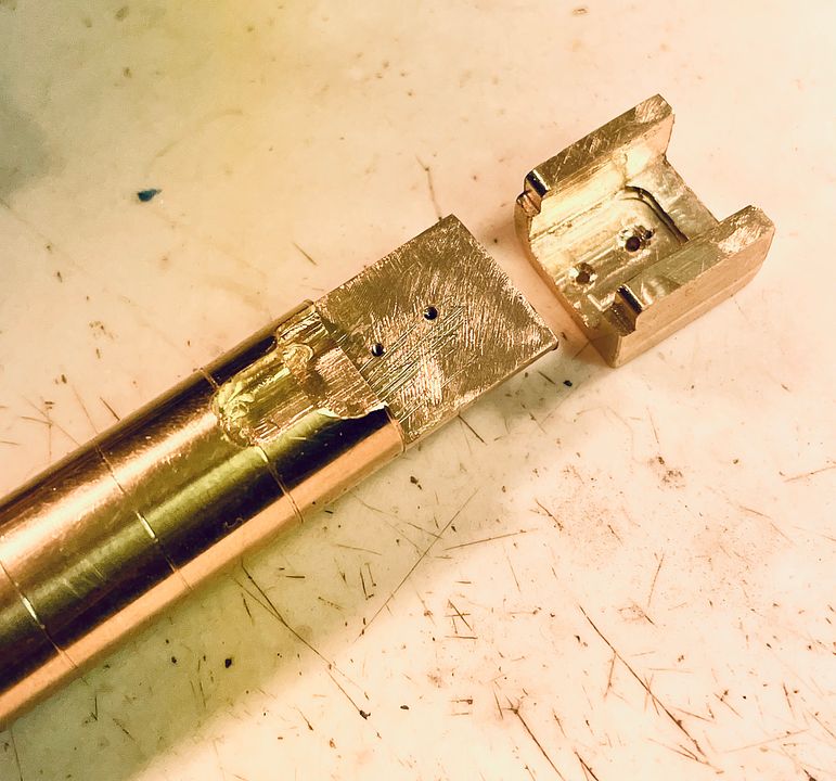
The sides are 0.5mm wider than the boiler and have a just-perceptible curve to them.
The whole assembly was then silver soldered together. The poor fit at the foundation ring and footplate will be covered by forward side extensions from the cab.
It is a very deep firebox, but that visual effect will be masked by the lower side pieces that will be part of the cab assembly.
She weighs 109g now. Smokebox saddle next.
Tim
Tim Watson
Western Thunderer
Does this prove that 2mm scale modellers are nuts?
Tim
Tim
Overseer
Western Thunderer
No, but you have put a hex on your model.Does this prove that 2mm scale modellers are nuts?
I am keen to see how you machine the smokebox.
Tim Watson
Western Thunderer
The bit of hex brass bar was drilled out and then bored to be a good fit on the smoke box.

The advantage of the hex bar is that it is easy to hold in a chuck and can be parted off to the required length. The front face was very carefully marked out for the two holes that would be the radiused corners of the smoke box saddle. I use a gramophone needle ground to a pyramidal-shaped tip. That way it is easy to ‘drift’ the centre mark to where it’s needed, rotating the tip to deepen it in the correct position.

The marked up block was easy to set up in the vice - an advantage of using the hex stock. It’s a bit difficult to visually ‘spot’ a 2mm drill in precisely the right place, so the drilling position was checked using a 0.7mm drill. The brass plug was a precaution against any lateral distortion when drilling with the larger size.

Once satisfied with the centering the holes were drilled at 2mm diameter.

The sides of the holes were milled away.

The side of the holes were used to guide a file as it cut down to the final position. It’s always useful having sharp files with safe edges.

The excess hex bar made a good handle as the base was carefully reduced in depth to maintain the correct height of the boiler and smokebox.

The unwanted parts of the bar were removed using a diamond slitting disc and the flange smoothed into the up right part of the saddle. This was also rebated at the sides to take the scale frames that are above running plate level.
She’s beginning to look like a Skittle Alley now.

Bit of a long post this one, but I thought some of my ways of working might be of interest. The next job will be to get it all bolted together.
Tim
The advantage of the hex bar is that it is easy to hold in a chuck and can be parted off to the required length. The front face was very carefully marked out for the two holes that would be the radiused corners of the smoke box saddle. I use a gramophone needle ground to a pyramidal-shaped tip. That way it is easy to ‘drift’ the centre mark to where it’s needed, rotating the tip to deepen it in the correct position.
The marked up block was easy to set up in the vice - an advantage of using the hex stock. It’s a bit difficult to visually ‘spot’ a 2mm drill in precisely the right place, so the drilling position was checked using a 0.7mm drill. The brass plug was a precaution against any lateral distortion when drilling with the larger size.
Once satisfied with the centering the holes were drilled at 2mm diameter.
The sides of the holes were milled away.
The side of the holes were used to guide a file as it cut down to the final position. It’s always useful having sharp files with safe edges.
The excess hex bar made a good handle as the base was carefully reduced in depth to maintain the correct height of the boiler and smokebox.
The unwanted parts of the bar were removed using a diamond slitting disc and the flange smoothed into the up right part of the saddle. This was also rebated at the sides to take the scale frames that are above running plate level.
She’s beginning to look like a Skittle Alley now.
Bit of a long post this one, but I thought some of my ways of working might be of interest. The next job will be to get it all bolted together.
Tim
Tim Watson
Western Thunderer
I often make pieces with sacrificial handles Simon: the scrap bits usually get used for something else.

Tim
Tim
Last edited:
Richard Taylor
Member
This is just superb. Learning a lot, but suspect that my fat fingers will never be able to put it into practice…
Richard
Richard
Tim Watson
Western Thunderer
Not much to show for today’s efforts, but the long engine is bolted up together at the front end.

It will need a couple of bolts at the fire box end to hold the boiler really well, but it is pretty stable already.

I expected to have clearance problems with the frames, but it all just clears and the rigidity of the components will prevent any unwanted contacts. Even so, the wheels needed clearance cutting into the boiler cladding (as per prototype).

Most importantly, it still works.
Tim
It will need a couple of bolts at the fire box end to hold the boiler really well, but it is pretty stable already.
I expected to have clearance problems with the frames, but it all just clears and the rigidity of the components will prevent any unwanted contacts. Even so, the wheels needed clearance cutting into the boiler cladding (as per prototype).
Most importantly, it still works.
Last edited:
Tim Watson
Western Thunderer
This post might be a case of teaching grandma to suck eggs, (especially on WT) but sometimes statements such as ‘fixing holes were drilled and tapped’ belies some of the challenges that these might present. Stabilising the firebox at the end of the running plate required two lugs. These were made by cutting two slots into the foundation ring of the firebox and making a wide brass bar (temporarily) across the bottom that was soft soldered in place.
The location of this on top of the running plate was marked with the inevitable gramophone needle.

The hole position was marked simply using a black pen dot. These holes are not mission critical, so great accuracy isn’t required. With TC drills there isn’t the need to centre mark or ‘pop’ the hole as their rigidity means that they self centre. The hole was drilled 0.7mm - tapping size for 14BA.
The boiler was then mounted on the running plate and the rear position held with a fillet of medium viscosity cyanoacrylate.

The assembly was then turned over and a 0.7mm drill aligned in the original hole and then taken right through the lug. The glue stopped anything from moving whilst drilling. In theory it could all be done in one go, but the chances of something moving are increased when the drill transits from the first piece of brass to the second.

Whilst in this position, the underside of the running plate was countersunk with a 1.7mm diameter drill to allow for the screw head.

Separating the pieces simply requires a well aimed scalpel blade to break the joint. The hole in the running plate was opened up to 1mm with a broach (clearance size for the screw) whilst the lugs were tapped 14BA.
Once assembled, the excess screw threads were cut off with Xuron side cutters and then unscrewed, that way the opening of the thread is preserved by being cleaned up with the tapped hole (similar to using a nut to do the same thing).

Last exercise was to cut off the bar in the middle.

I was in two minds whether these lugs were really needed as the boiler could easily have been centred using the cab front. However, it does now give a good solid reference point against which to build the cab. The lugs will be covered over by a front extension of the cab.
That is a very long-winded description of drilling two holes which may seem excessive, but the technique does maintain accurate positions for components. I don’t think I have seen such things actually described anywhere - probably because it’s a bit like watching paint dry…
Tim
The location of this on top of the running plate was marked with the inevitable gramophone needle.
The hole position was marked simply using a black pen dot. These holes are not mission critical, so great accuracy isn’t required. With TC drills there isn’t the need to centre mark or ‘pop’ the hole as their rigidity means that they self centre. The hole was drilled 0.7mm - tapping size for 14BA.
The boiler was then mounted on the running plate and the rear position held with a fillet of medium viscosity cyanoacrylate.
The assembly was then turned over and a 0.7mm drill aligned in the original hole and then taken right through the lug. The glue stopped anything from moving whilst drilling. In theory it could all be done in one go, but the chances of something moving are increased when the drill transits from the first piece of brass to the second.
Whilst in this position, the underside of the running plate was countersunk with a 1.7mm diameter drill to allow for the screw head.
Separating the pieces simply requires a well aimed scalpel blade to break the joint. The hole in the running plate was opened up to 1mm with a broach (clearance size for the screw) whilst the lugs were tapped 14BA.
Once assembled, the excess screw threads were cut off with Xuron side cutters and then unscrewed, that way the opening of the thread is preserved by being cleaned up with the tapped hole (similar to using a nut to do the same thing).
Last exercise was to cut off the bar in the middle.
I was in two minds whether these lugs were really needed as the boiler could easily have been centred using the cab front. However, it does now give a good solid reference point against which to build the cab. The lugs will be covered over by a front extension of the cab.
That is a very long-winded description of drilling two holes which may seem excessive, but the technique does maintain accurate positions for components. I don’t think I have seen such things actually described anywhere - probably because it’s a bit like watching paint dry…
Tim
Last edited:
michael mott
Western Thunderer
Watching paint dry or not it is interesting at the scale you are working at.
Michael
Michael
Tim Watson
Western Thunderer
Attention has now turned to the cylinders. These will be soft soldered to two pads which are, in turn bolted through the frames. The fixing studs are 16BA silver soldered in the brass block. The reasons for the square cut outs in the PCB spacer are now apparent, as they give room for the nuts. The cylinders will have polished steel end caps, as per the prototype, and it’s fortunate that the rear one is very simple, which will make machining the slide bars rather easier.

The cylinders are bored 1.5mm to take the front and back fittings. It’s also useful for checking alignment using a sighting rod. The cylinders are currently 0.5mm too wide on each side, but there should be ample clearance to bring them in to scale width.

The next job will be to file off the top of the cylinders to allow for their inclination, then solder them on to the pads.
Tim
The cylinders are bored 1.5mm to take the front and back fittings. It’s also useful for checking alignment using a sighting rod. The cylinders are currently 0.5mm too wide on each side, but there should be ample clearance to bring them in to scale width.
The next job will be to file off the top of the cylinders to allow for their inclination, then solder them on to the pads.
Tim
Tim Watson
Western Thunderer
Slight change of tack, but Copenhagen Fields will feature in the next episode of ‘Hornby a Model World’ on the Yesterday Channel (Freeview 27) on Monday 30/1/23 at 2000.
You will find out how this happy little scene was made:

As well as our trip with CF to the 2mm Association Derby exhibition in June ‘22.

Tim
You will find out how this happy little scene was made:
As well as our trip with CF to the 2mm Association Derby exhibition in June ‘22.
Tim