As many of you will be aware, Hornby have produced a rather good Coronation set in 4mm scale with a streamlined canvas fairing cleverly modelled. I was kindly given images of these by Tony Wright & Jesse Sim to work out the mechanism, actually confirmed by seeing one in the flesh at the MRC. I thought this clever idea could be made to work in 2mm scale.

My previous streamlined Silver Jubilee set had thin rubber fairings (dental dam) fixed at one end and tucked into the neighbouring coach: unfortunately these have perished over the years. The Coronation is different because the canvas fairings were painted to match the body colour and so a solid structure would represent this rather better - as per Hornby.
The coach bodies therefore need to separate when traversing a curve: this is achieved by a mechanism based on two curved slots engaged by pins at each end of the bogie with the articulated pivot slotted to allow extension. As the bogie enters a curve, the pins move into the opposed curved sections and so the carriage bodies move apart on the articulation slot.

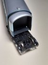
I realised that fabricating such an extending mechanism would require fairly accurate cutting out; some simple drilling jigs were therefore made to ensure commonality between the chassis and the bogie. As a reference, the centre line of the chassis spar was scribed between the articulation point and the conventional bogie pivot. The articulation end was then stabilised on a drill shank in a block of Tufnol. This also located the steel drilling jig and its centre line notch aligned with the scribed line, finally being held with a drop of cyanoacrylate adhesive at the free end. The first centre hole was drilled, then a pin placed in the hole to further stabilise the jig whilst the other two holes were drilled either side, being at the extremities of the prospective arc. (The nearer set of holes in the steel jig are for extra heavy-weight 10’ bogies.)
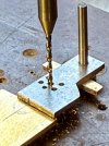
The two arcs between the holes were cut out with a piercing saw and filed to allow a 1mm diameter rod to freely pass through the shape. At this stage the articulation pivot hole had not been elongated to allow lengthening.
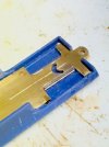
The same steel jig was then located within the underside of the bogie and the drive pin holes drilled at each end, directly above the axle in the midline.
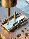
Some provisional pins were made from 10 & 12BA bolts for the main bogie pivot shaft and the two drive pins respectively. The streamlined fairing was made from a 4mm thick sheet of very hard grade Tufnol, with two pegs milled into the bottom, a centre hole drilled and two 14BA studs drilled, tapped and Araldited into the two pegs.
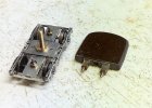
[/URL]
The two holes for the fairing, either side of the bogie pivot post, were drilled using a steel and brass jig for drilling the stud holes. This was held in place (temporarily) with a 10BA nut and bolt whilst the 0.8mm holes were drilled (subsequently reamed to 1mm clearance).
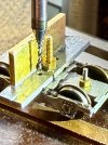
The same jig was used to drill the Tufnol fairing it having already been drilled 1.7mm clearance for the central 10BA bolt, using this hole to locate the jig. The assembly was clamped in the vice, simultaneously holding the fairing for drilling as can be seen in the image below.
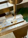
The bare bones of the articulated carriages worked together broadly as expected when placed on an 18” radius test track; they were also acceptable with the 3DP under frames and fairing in situ.


In order to work smoothly the fairing needs to be bevelled on its outer corners and the inverse on the carriage bodies. These were filed and smoothed accordingly.
3307a42c-aaf4-4767-a782-f6b85a35dc22.jpe
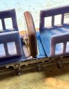
The mechanism at its most extreme can be seen with the temporary bodies assembled on the 18” test track. It looks as if the fairing is herniating sideways like a slipped disc, but it actually stays in position on the bogie and is lost within the carriage body.

It runs well enough on the test track (interesting beaver tail…), but the acid test will be trying it out on the layout.

The carriages are not a new streamlined LNER / GNER suburban service but the core for the etched sides for the Coronation set itself. Our curves are much more generous on CF than train sets so we might get quite a good prototypically subtle result, especially as our visible tracks are virtually straight.
Once I am content that the prototype is working as expected, then the other three pairs will be made. The inter articulated-pair ends will also be fully streamlined, probably much as Hornby have with their sets. It has certainly made me stretch the little grey cells getting this far.
If anyone has made it to the end of this post: well done! You deserve a New Year celebration drink.
All the best for 2025
Tim


 [/URL]


