The Heybridge Railway, 1889 to 1913

spikey faz

Western Thunderer
Out of interest is there any reason why an 0-4-2 cannot be treated as an 0-6-0 minus the rear coupling rods? All three axles running in normal axle boxes with a bit of side play on the middle axle to assist on curved track. Might be easier to arrange than a radial axle?

I know that one of the Stroudley Terriers (Boxhill) was temporarily converted to run as a 2-4-0 with smaller front wheels. Would the engineers have gone to the trouble of putting in a radial axle set-up?

Mike
 

Richard Gawler

Western Thunderer
A mate suggested building it as an 0-6-0. At the time I thought this was a bit ambitious for a first attempt at a loco build (I had after all bought a kit for an 0-4-0), so I thought do an 0-6-0 with its rear rods removed and running as an 0-4-2. But I had the Lomac wheels to hand and a third set of driving wheels was another £24 to spend on what is really a test piece for me to show myself I can build a loco from a well-known good kit.

My book on crane tanks has lots of 0-4-4 and 0-4-2 examples. An 0-4-4 seemed too ambitious because of the weight distribution and so Nellie is an 0-4-2. She runs beautifully and even copes with my Setrack point with its 1020 mm radius and 31 mm gauge.

I expect you are quite correct, the engineers of the day would not have used a radial axle. However, if I can use one and see that it tightens the line of the loco on a sharp curve then this ought to reduce instances of buffer lock (shouldn't it?) and if so I will feel I have achieved something new even if this wasn't a particular objective when I began.
 

spikey faz

Western Thunderer
In the book 'Crane Locomotives' by John Woodhams there is mention (and a drawing) of a crane loco based on a LSWR B4. As Dapol are bringing out an O scale B4 later this year I might get one and modify it accordingly to an 0-4-2CT. Just not sure whether to follow your lead with the trailing axle, or keep it simple. :)

Mike
 

Richard Gawler

Western Thunderer
Well, I will be happier with my arrangement after I have seen the loco run through some complex pointwork with success. This can happen in the next month or so on one of a couple of other people's layouts.

Do bear in mind, my Nellie is a bit of a test bed for me, certainly a proving ground for what I can do. I expect many folk will be thinking, I could have bought Jim's J79 and built it as a crane tank . . . but doing this would have forced me to follow a prototype when what I wanted to do was find out what I could achieve with a simple kit and some extra brass.
 
Last edited:

allegheny1600

Western Thunderer
Hi Richard,
It’s taken me some time to catch up, sorry! Phew, you have been busy and successful with this, it’s turning out really well. Judging by your video just a little while ago, the running is beautifully smooth - it’s really something to be proud of.
Cheers,
John
 

Richard Gawler

Western Thunderer
Progress has been good until today and I stopped because of the heat. I wanted to laminate two coupling hooks together. One immediately slipped crooked. The blowlamp had run out of gas and I thought I was going to keel over refilling the butane with all the windows closed. I separated the hooks, one fell onto the floor and I called it a day. I have just found the lost hook, along with bits and pieces from models I was building 6+ months ago :)
 

Richard Gawler

Western Thunderer
DSC_9979.jpg


I like the idea of the second skin to house the glazing. I may pinch that one at some point, especially for my crane tank as like you I will have a spare cab rear.

I have a bit of a dilemma. I can see three possible approaches:

1) Paint the model. Install the glazing and scrape off enough paint to solder on the roof.
2) Install the glazing and the roof. Mask the glazing before painting.
3) Make the roof a detachable subassembly, perhaps some prongs going down into the gap between the skins.

None of these is particularly appealing at the moment.

I wonder what an experienced model maker would do?
 

Richard Gawler

Western Thunderer
I’d vote for #3

Yes.

It's funny how these things seem easier when someone suggests a route to try, but number 3 is probably the most flexible. If it works, great, If it goes wrong I can cut a new roof from brass sheet, and if it goes wrong again then revert to option 1. Option 2. just looks like making hard work of things.
 

Richard Gawler

Western Thunderer
You could solder in an "under-roof" which matches the intended roof profile, but stops just short of the glazing slot - and then attach the roof "proper" to this using adhesive after the model was painted?

That would be my way of tackling it too.

Yes. This was easier than I expected.

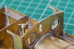
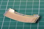
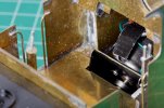
The kit roof is half-etched over almost all of its area so quite fragile. I took a strip of 16 thou brass, annealed it and curved it to the wanted profile. The cab roof was easy to curve to match. Soldered the two together on all four edges. Added two small tabs of brass to drop between the two layers of cab front.

DSC_9985.jpg
This is actually quite sturdy, but I can still make small adjustments to the curvature.

DSC_9980.jpg
Not perfect, but not bad either.

I think I should stop here. After the model is painted, I can fix the roof on with some glue on the two tabs, and fill the hairline cracks with some cotton thread or similar on the inside.

We are told we should build models as sub-assemblies. I now have these:
  • body
  • cab roof - fixed with tabs into slots
  • boiler backhead - intending to use Blu Tack
  • crane base panel - magnets
  • crane jib - pivot pin
  • chassis including all electrical wiring - two machine screws
  • trailing wheels assembly - kept captive by one machine screw
  • additional weight for trailing wheels - press fit over top of trailing wheels assembly
The remaining parts to fit are dwindling to nothing :)
 

Richard Gawler

Western Thunderer
I finished off the buffer beams yesterday. This post is slightly out of sequence, I did these before the cab roof.

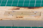
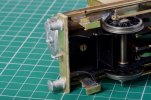
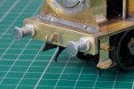
The buffer beams looked a bit flimsy so I thickened them up with some 1/16 inch obechi and new outer layers from brass.

DSC_9974.jpg
I made up the outer layers as a pair, they don't need to be identical but I found it easier to file the edges square this way. I made the holes first and then filed down the edges so the holes ended up in the right place.

DSC_9994.jpg
The new buffer beams are a sandwich glued together with Araldite.

DSC_9991.jpg
The kit comes with two coupling hooks. I laminated these together to make the hook for the front of the loco. At the back I used a Peco Parkside hook soldered onto a scrap of brass and this all filed to shape.

I had a lot of trouble trying to solder this hook into place, the solder would not jump across. Thinking about it now, I suspect some Araldite had crept up inside the slot and was a perfect solder resist. The hooks are soldered solid onto the inside layers of the buffer beams. The buffers went on with Araldite too.
 
Last edited:

Richard Gawler

Western Thunderer
DSC_9998.jpg
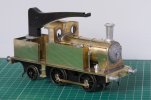
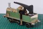
Nellie prinked up with Solvol Autosol and posed this morning with temporary chimney and temporary oil can.

I removed the front footsteps, they seemed to spoil the look of the loco.

The side of the crane base bears witness to a plastic soft-faced clamp I attached while I soldered the crane base to the footplate. I need to be more gentle. I might end up with the name plate here.
 

Richard Gawler

Western Thunderer
I borrowed a loco builder box by Poppy's Woodtech from a friend. The builder box uses extended axles (supplied with the box) and the loco coupling rods to locate the axle bushes in the frames ready for soldering.

. . .

View attachment 166175

I am full of enthusiasm for the Poppy's loco builder box (I have used both 4mm and 7mm versions) but there is a small caution I want to mention.

All of Jim Mcgeown's six-coupled chassis have the centre axle raised slightly, about 1/4 mm. This helps to make for good running with a rigid chassis but of course it rather goes against the grain of the Poppy's box, which specifically aims to get all of the axles in line with each other. I expect other kit manufacturers do this as well.

I am thinking about this for when I come to build my next loco. Perhaps the solution is to set up the bearings for the centre axle with the bearings for one of the outer axles. Remove the axle for this outer axle and then do the other outer axle. Or, make two vertical slots in the box close to the round holes to hold the centre axle.

I wonder if anyone here has come up against this?
 
Last edited:

Richard Gawler

Western Thunderer
During the test run yesterday, Nellie never derailed and never refused to move except through wheelspin i.e. the motor always ran when requested. Power was from an ancient Duette, the case of this was getting hot enough to fry eggs but it carried on regardless.

Bringing Nellie back home she did not run very well. This was because the wheels were rather grubby! So I cleaned them. One of the crankpin nuts was at the very tip of its crankpin, I really must buy some proper 12BA spanners and not rely on my bit of brass tube squashed down at the end.

I unmeshed the worm gear, trundled the chassis back and forth, and found no tight spots or indeed free play. So I think the powered part of the chassis is as good as I can get it. I have taken the side rods off (and marked them!) for painting.

The loco ran for about half an hour yesterday so probably most of 15 scale miles. It is a bit sad to think, this is as much as she might manage in a year on a home end-to-end scheme. However, the moving parts are surely starting to bed in.
 

Richard Gawler

Western Thunderer
Interesting to see the wheelspin, what do you think was the cause? Does the loco need more weight?

Michael

The wheelspin happened at two locations on the railway were there is a slight gradient. The railway is a demountable affair - the builder/owner has used those adjustable legs for kitchen cupboards to support the boards and these legs are standing on scraps of vinyl flooring on the lawn, but it still needs a lot of care to get the structure truly level.

I suspect the gradient is pretty minor - perhaps 1:50 or 1:75 and not as steep as implied in my video - but it is enough to get Nellie to pick up her heels with a heavy train. The four coaches weigh about 4 kg in all, they have roller bearings and are very free-running but there is still a lot of dead weight to get moving after the loco looses traction.

I think, I have found the limit of what is essentially an 0-4-0 with an 1833-pattern motor can achieve using standard parts. In other words, two coaches or possibly three would not cause a problem. I suppose, this is much like the way prototype needs bigger and more powerful locos for heavier trains.

DSC_0022.jpg

I have put 134 grams of lead into the side tanks, half each side. This is located well forward. I have tried to show this in the photo. You can see the back of the worm where it dissapears under the cab floor so so you can work out roughly where the driven axle is. The C of G is now about 10 mm in front of this axle.

I am reluctant to add any more weight. The loco is now up to 496 grams minus crane and some small castings, so it is going to be 550 grams or so when finished.

I do wonder whether the crank pins could be better. What I mean is, the motor is delivering its power to the driven axle through a small-ish diameter worm onto a broad worm gear and this is pretty efficient. But the transfer of drive to the front axle is through the 12 BA crank pins and bushes. 12 BA seems ever so slender to be asked to transfer so much power? @Rob Pulham has written about tapping the crank pin bushes for 10BA crank pins. I do wonder, if these would be more effective. Then again, Nellie will rarely move six wagons on my layout at home (when I stop building model trains and build it . . .) and I know she can move 10 small Victorian wagons carrying weights to make them the equivalent of 22.

There is also the matter of the three-wheels-on-the-track stance of a loco with a rigid wheelbase. This probably means, when wheelslip happens the loco only really has the practical use of two wheels (being two on the same axle) to get it moving again? If it had a rocking front axle, this would make sure there were four wheels on the track so this would seem to double the useful contact area. On the other hand, I am rather reluctant to go filing out the axle bushes to provide the rocking axle; they are made as a precision part and it seems a bit daft to go to them with a file.

Maybe someone knows about benefits of larger crank pins. They must be a lot sturdier, but I don't really know what benefit there will be in having the bushes locked onto them. Also, how much the rocking axle would help to improve traction.
 
Top