The Heybridge Railway, 1889 to 1913

Richard Gawler

Western Thunderer
DSC_0528.jpg

This model never made it to a pristine condition. Having painted the sides and underframe I masked everything with some care, picked up the wrong rattle can and sprayed the roof. And I didn't notice until I had let it start to dry and took the model back to its siblings. So then, trying to take a short cut I partially masked the model and propped up some bits of card while I applied the wanted colour.

Needless to say, a tiny bit of the new roof colour made its way onto the sides. So I ended up having a go at weathering the underframe and the lower sides to blend everything together.

DSC_0542.jpg
Party piece.

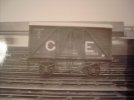
This is an unfitted wagon. The inscription is slightly tongue in cheek but represents how I would like my layout to be. This is very much an ex-Midland Railway van.

I am using a Humbrol airbrush, the single-action sort you can buy for about £15. It works fine for putting on slabs of colour like on the sides of the van but my attempts at weathering look a bit splattered. This was with the air pressure turned right down to 10psi. I want to do something more subtle, I suspect I have reached the limit of what I can achieve with this airbrush.
 
Last edited:

Tim Birch

Western Thunderer
An alternative to the tin and boiling water technique for forming a roof curve is the use a sheet of Slaters' planking plasticard. This can be cut as a rectangle easily using the planking grooves as a reference and then formed into a gentle curve along the plank lengths. The rear side of the sheet forms the upper surface of the roof and this can then be sanded when in situ to give as much or as little impression of planking as is required.
 

Richard Gawler

Western Thunderer
An alternative to the tin and boiling water technique for forming a roof curve is the use a sheet of Slaters' planking plasticard. This can be cut as a rectangle easily using the planking grooves as a reference and then formed into a gentle curve along the plank lengths. The rear side of the sheet forms the upper surface of the roof and this can then be sanded when in situ to give as much or as little impression of planking as is required.

This sounds ideal, I will give this a try when I re-roof my break van. Many thanks.
 

Simon

Flying Squad
If you scribe plank lines on a piece of Plastikard to replicate the planks (from which all roofs were formed before plywood etc) you will find that it naturally assumes a curve. Then roughly sand the upper surface to remove the kerf, and cover with tissue/old shirt/whatever to represent the roof covering.

The Olfa scribing tool is brilliant for this and lots of other jobs, highly recommended.

(Olfa PC-L) £13.19 - Olfa PC-L Plastic Cutter

Proper job!
 
GWR 4-plank wagon (1880s) . . part 3 axleboxes and brakes

Richard Gawler

Western Thunderer
As one of the non-casual viewers I will have to point out that all the GWR 4-plank wagons of this type were rated to carry 10 tons. In practice they rarely did carry anything like the maximum load especially in merchandise traffic. The tare weights were typically in the 5-0-0 to 5-6-0 range. By the time the company got around to fitting them with oil 'boxes (c1900), the G . W . R lettering was on the right hand side – and rather more spaced out than in your example. The door banger plate is surplus to requirements on the non-brake side, and the brake shoes should be 'handed' (ie without the bottom lug). Other than that it's a lovely model!

Sorry!

Returning briefly to my GWR 4-plank wagon, I have had a go at the axle boxes and the brake shoes.

DSC_0520.jpg
I have filed down the moulded axle boxes as far as the faces of the brass bearings and squared up the sides of the remaining mouldings to make them into a rectangular shape. The new fronts are 1 mm thick styrene with the lids made from 1 x 1 mm styrene rod glued on and then filed to shape.

DSC_0547.jpg
The brake shoes are now 'handed' too.

The left-hand G W R (which I wanted in the first place to emphasise the period of my layout) is now on a more appropriate-looking wagon. The 8-ton capacity remains "correct for my project" (see my post no.291) and if this particular variant hasn't been recorded in the history books then I can only imagine I must have modelled an undiagrammed wagon!

I want to call this wagon finished now except for its loads and weathering.
 
Last edited:

Richard Gawler

Western Thunderer
P1040456.JPG

Plate 352 from "GWR Goods Wagons" by Atkins, Beard and Tourret.

There is one vee-shaped support between the brake lever and the mechanism of the brake, and I feel this is what I have represented on my model. See also my post no.99, which shows the moulding for the brake gear unpainted.

I haven't found a photo of the single strut either but the GWR reference section of my library is meagre. Just a book on iron minks which I can't find right now, and a borrowed copy of Atkins et al.
 

Richard Gawler

Western Thunderer
Richard,
If you come across the 3 Aitch 7mm Cattle Van, grab it as it is an LTSR prototype and would fit in rather well with your Heybridge scheme.
The 3 Aitch stuff is quite "rustic" but full of character, I must try a bit harder to add some to my collection heap of shelf queens.
Rob
DSC_0549.jpg
Like buses – I posted a small ad here and three have come along together. One completed and with its original plastic wheels, one mostly built and and a third one just started. I will put these to one side for the Winter.
 

Richard Gawler

Western Thunderer
First annual report!

When I finished my Slater’s rectangular tank wagon in September last year, I promised myself I would build a wagon every month for a year or give up on 7mm scale; and the ex-MR van is my twelfth. I fitted a crane tank and a platform shelter into this year too. Fundamentally, I am pleased with all of the models I have made. The weakest is probably the Jubilee wagon (3.5 mm too long and no pin points on the axles) but I have bought a fresh kit to try this idea again.

I am building a might-have-been railway and to my mind it should have might-have-been trains, or at least slightly vague representations of them. I mean, the railway would seem a bit odd if it had specific prototypes working on it, day in and day out, when we know these prototypes really worked somewhere else.

The mix of wagons I have assembled is actually pretty fair to represent my imaginary railway; the only real shortfall is some GER stock for through workings from the Witham to Maldon branch. There are kits out there for some of these but of quite an advanced nature, so these wagons can come along in their own time when I feel I am ready to tackle them.

Before then I have a couple of larger models in mind: a brake third coach and a GER Y14. Both from Jim Mcgeown. I am gathering up specifications and photos of candidate Y14s to start the loco after the clocks change, and can use the coach before then to get some experience with the micro flame torch.

The Y14 will be a fairly involved build for me, so I expect I will drop out of it from time to time and this will be a good opportunity to work up the cattle wagons. I need to have a think about trackwork too. After I have built my first B6 I expect I will get a reality check on how much model railway layout I can actually have. I have made a start by reworking a Marcway 6ft point into something near to 0-MF, this might find a place mostly buried in ash on the layout.

My model making got a bit intense during the summer time and I want to slow down the tempo a bit. So posts here may get a bit less frequent. But please, everyone, thank you for all of your support and advice and ideas during my first few months on WT.
 
A plan for the layout and building its two turnouts

Richard Gawler

Western Thunderer
A pen friend has sent me some unwanted track including a brand-new turnout kit. Now, I envisage my layout will have code 100 FB rail laid directly onto 9 ft sleepers but I can use their track in a fiddle yard or for a diorama or other test piece.

DSC_0575.jpg
Things haven’t got off to a terribly good start. The ready-made common crossing was clearly asymmetrical, the feeler gauges say 1.75 to 1.80 mm on one side and 1.65 to 1.70 mm the other. So I have taken this to bits to rebuild it with 1.5 mm flangeways. At the moment I am trying to fathom out how to put the vee back onto the wing rail assembly.

The vee had a sharp nose and I have filed this down to about 0.4 mm wide.

The stock rails supplied are too short to build the kit on a curved formation so I stripped down a piece of the gifted track to get some longer ones. The check rails are too short as well but I can make new ones. I haven't dared look at the switch rails yet.

On the bright side, pre-grouping turnout timbers are consistently longer than modern ones, so shorter ones supplied in the kit all fitted onto the template. I needed only one extra timber (from Peco) to provide the very longest one.

DSC_0579.jpg
For the avoidance of any doubt, I do not know how to use track plotting software beyond AnyRail. I know how to install a Windows program and run it, change the track settings to “0-MF” and “pre-grouping timbers”, and make a printout. The curved left-hand arrangement supplied as a default template looked pleasing so I am building my kit on this.

I have borrowed an entire shelf from my spur shelving installation to provide the board for assembly. The offcut of aluminium angle in the photo measures just about a perfect 1.5 mm thick, should be useful.

At the end of day one (three short modelling sessions) I have all of the timbers and the first stock rail in place. If this was copperclad I would have finished it by now! However, I must learn new techniques and the sight of the rail sitting in its individual little chairs is certainly quite pleasing.

I am taking Nellie to West Bergholt this afternoon if anyone reading this would like to see her.
 
Last edited:

Richard Gawler

Western Thunderer
Sorry to say that picture of a single V hanger has been retouched and the single inner hanger whited out. The GWR, GER and Midland all used a similar single strut.

Hi Mike.

I have found my copy of Lewis et al, "all about GWR Iron Minks" and the single strut is clear to see in photos and on the drawings. It's funny how detail becomes more noticeable when you know what to look for.

I can add this strut to a few of my wagons including my Minerva iron mink (I have single-sided brake gear on this) as well as my GWR open.

Thanks for this.
 

Mike W

Western Thunderer
Sorry to have caused you more work Richard! I enjoy your thread and without trying to hi-jack it too much I'd be interested in comments from some of the more engineering-minded experts on here. So far as I can see that single strut merely holds up one end of the short rod/bar and is free to move along the wagon, to compensate for uneven wear on brake blocks, pins etc. Seems to me a better idea than the later double V hanger which was fixed rigid. So why was it discontinued?

Mike
 

Richard Gawler

Western Thunderer
If you have two of something 1.5mm thick, you could put each against a wing rail and then insert the V until all three are tight to each other. You should then hopefully have 1.5mm flangeways.

Thanks for this - I've got some 1.5 mm aluminium to use as shims.

My difficulty is comprehending how to fix the common crossing onto the timbers - the rails need to be sitting 1+ mm above the tops of the timbers. And all of the rail fixings are to be created by carving up ordinary running chairs.

I think what I will do is assemble the crossing onto a piece of brass sheet broad enough to span two timbers. Trim this piece down on the outside flush with the bottoms of the wing rails. Glue it onto the timbers with shims as needed. Then with the crossing fixed at the right height, cut up scraps of chairs to finish the job cosmetically. This will create a sturdy job and a derailed train hitting the vee at speed shouldn't dislodge anything.

I will lose daylight looking down between two timbers but looking at the way Peco construct a Setrack point, with solid plastic all around the crossing, it won't show up unless I look for it.
 

Richard Gawler

Western Thunderer
Sorry to have caused you more work Richard! I enjoy your thread and without trying to hi-jack it too much I'd be interested in comments from some of the more engineering-minded experts on here. So far as I can see that single strut merely holds up one end of the short rod/bar and is free to move along the wagon, to compensate for uneven wear on brake blocks, pins etc. Seems to me a better idea than the later double V hanger which was fixed rigid. So why was it discontinued?

Mike
Hi Mike.

I have no concerns when the thread deviates onto something I have a chance of being able to put right!

Sitting beside the club track yesterday, I did notice every model wagon running past me had one vee hanger on the outside and one vee hanger or nothing at all on the inside, never a single strut. I think they were all kit- or scratch- built. Dapol and Minerva haven't put them on their PO and GWR models in my possession. So I guess these single struts haven't caught on widely?

I am quoting you here to get your input onto my the fresh page, so the experts can see it more easily and perhaps discuss it while I carry on with my B6 :)
 

Richard Gawler

Western Thunderer
I suspect wagon experts are waiting for me to make something so they can suggest further improvements :rolleyes:

So back to the B6.

The common crossing has a third "flangeway" being its throat. If the wing rails were bent at perfect sharp angles, the throat would be the same width as the two flangeways, 1.5 mm for 0-MF. But because the wing rails stretch to form a radius at the throat, and both rails have to align with their respective sides of the vee (have I lost everyone yet?) the gap here ends up slightly wider. I didn't measure the width of the original throat but choosing to rebuilding the assembly to alter the flangeways means I rebuilt the throat to suit.

DSC_0595.jpg
I have rebuilt the crossing on a piece of brass sheet.

I annealed the brass after cutting it out so I could adjust its flatness. I attached the vee and then the first wing rail.

The photo shows the arrangement after I added the second wing rail. Top left is my bradawl, shoved into the work surface to give me something to push against. There is a strip of 1.5 mm thick aluminium to align the second wing rail (to the right) with its associated side of the vee. I have my 1.0 and 0.5 mm feeler gauges to set up the second flangeway and the handle of a small file to push everything into place while I soldered it up.

DSC_0601.jpg
Then I added a support for the throat (top right), trimmed the brass sheet to size and cleaned up the job.

DSC_0575.jpg
Original (left) and rebuilt (right).

Sorry I don't have photo editing software to readily alter the size of one image relative to another. Just "Paint" to paste one in beside the together.

The original clearly has one flangeway larger than the other. On my rebuilt version I fear the left-hand flangeway is still not perfectly straight and opens out towards the throat. This is probably because the bend in the rail at the throat is a little too shallow. However the quest for perfection has to stop somewhere and I think this will work.
 
Top