The Heybridge Railway, 1889 to 1913

Richard Gawler

Western Thunderer
Thank you for your kind comment. The camera is a Panasonic Lumix DC-TZ90. I bought it from CameraWorld in Chelmsford, I wanted something which looks nondescript so I can take photos without looking like a journalist. All of the pictures of the J15 were taken with the camera in its "program mode", a few had the flash turned on to fill in the shadows.

The camera works really well outdoors, it only really shows up its limitations if you do close-ups of model trains. I find the ergonomics of the controls pretty much impossible to use, it has one "control ring" which has to serve to set the aperture, shutter and manual focus, so it sits in its program mode all the time.
 

Brian McKenzie

Western Thunderer
. . . . camera is a Panasonic Lumix DC-TZ90 . . . . it only really shows up its limitations if you do close-ups of model trains.

This camera can take and process focus-stacked images within. Keen to see how well this performs for model work.
Good luck with wrangling the settings in the torturous menu though.

-Brian
 

Phil O

Western Thunderer
This sounds like enough to persuade me to alter the frames. I can cut pieces of brass to slip in behind to represent the firebox and drill holes for the valve and door. The frame detail near here is going to be a bit sketchy because there is a motor and gearbox nearby, but I think the rework will be worthwhile.

The bit under the foundation ring of the firebox, is the ash pan and that is the same size as the inner firebox, hence it being slightly smaller than the external length of the outer firebox.

HTH.
 

Richard Gawler

Western Thunderer
I have been working my way through the detailed essays on these locos written by Lyn D Brooks and published in the GER Society Journal in 1983, and I have come up with two lists of the subjects I need to tackle :)

References

Brooks, Lyn D, T. W. Wordsell's Class Y14 0-6-0 (LNER Class J-15), Great Eastern Journal October 1983
Brooks, Lyn D, J. Holden's Class S23 2640 Gallon Locomotive Tender: Part One, Great Eastern Journal January 1984
Brooks, Lyn D, J. Holden's Class S23 2640 Gallon Locomotive Tender: Part Two, Great Eastern Journal April 1984
Gardner, J, GERS drawing no. L46 and supporting notes, S23 Standard Small Tender, GERS

Model of class Y14 locomotive
  • An example from one of batches S28 and X28 (built 1891 to 1892)
  • The locomotive is in its original condition (this seems fair for a 1890s setting), and so it is mostly unchanged from the original Wordsell batch of 1883, and has not, for example, been reboilered
  • This is a freight locomotive
The details I especially need to watch for are these. The letters in brackets ( ) are references used by Brooks
  1. Two-ring boiler (B) (The three-ring boiler is possible by re-rolling the wrapper inside out)
  2. Sloping grate (D)
  3. Deep frames with oval cut-out beside grate (D)
  4. Low-sided cab with deep cut-outs (E) : kit option
  5. No locomotive brake or train brake, hand brake on tender only : modify kit frames
  6. No steam heating (of course) : omit kit parts
  7. Lamp irons of the spike type pattern introduced by James Holden (M) (fitted 1886 onwards)
  8. Spherical blower valve, mounted at end of handrail on right-hand side of smokebox (N) :
  9. Hollow handrail and control wheel at end of handrail, inside cab (N) : include wheel but ignore extra thickness of hollow handrail
  10. Dished smokebox door (T) : use part from Laurie Griffin
  11. Built-up style smokebox with plain front (X) (flanged type from 1899) : no action
  12. Parallel-cased buffers (c) : use Markits buffers (shallow bases)
  13. One Roscoe lubricator, usually but not always on right-hand side of smokebox (g) :
  14. Plain side rods (fluted from 1913) : use kit parts inside-out
  15. Chimney of GER pattern : kit option
  16. Shallow cab roof profile: kit option
  17. Ramsbottom safety valve : kit option
  18. Whistle on base of safety valve (part of the Ramsbottom design) : use alternative whistle supplied in kit
  19. Black livery with lining, small G E R lettering on tender : check period photos
  20. The boiler band located at the front of the firebox goes around the boiler and not down the sides of the firebox : check space for motor, shorten firebox, relocate firebox front, fill gaps created in boiler
  21. Unbalanced wheels : omit balance weights provided in the kit
  22. No washout plugs (1930s addition) : omit washout plugs supplied in kit, fill alignment marks on firebox wrapper
  23. Separate handrails on front of smokebox and sides of boiler : drill holes to suit new handrail knobs
  24. Early style cab roof : construct a new roof
Bonus feature: a Macallan blast-pipe, actuated by a crank on the left-hand side of the smoke box and a lever linking this back to the cab, was retro-fitted to these locomotives during the 1890s, so is a possible option (R) : omit for simplicity

Model of S23 tender
  1. Asymmetric wheelbase, 5ft 6in + 6ft 6in : provided by design of kit
  2. Side frames with D-shaped slots : use parts from Alan Gibson kit for an E4
  3. Narrow buffer beam (7ft 8in wide) : provided by design of kit
  4. Hand brake : provided by design of kit, but add a new handle from wire
  5. Front footsteps mounted on the frames not a separate backing plate : provided by design of kit
  6. One or two toolboxes(*), placed directly on top of tank without wooden packing : provided by design of kit
  7. Holes in rear buffer beam left from removal of safety chains : drill buffer beam to suit
  8. No coal guards (1926 onwards): omit kit parts
  9. No water scoop (1897 onwards) : omit kit parts
  10. No rack for headcode discs (fitted from c.1904 onwards)
  11. No water gauge (fitted from c.1904 onwards)
  12. No partition for fire irons (fitted from 1906 onwards) : omit kit partition
(*) The John Gardner drawing of the tender (GERS drawing number L46) states, "toolbox both sides until c.1923 usually one only LNER" but Brooks suggests there could be one or two in GER times, and with no standardisation of which side or the orientation.

It's nice to see, many of these details are things the model won't have. My model will be simpler than one representing a loco in the 1960s.

Revisions

I am editing these lists as and when fresh details or corrections come to light . . .

7 Nov 2022 : added item 20, the need to locate the boiler band in front of the firebox correctly
14 Nov 2022 : added item 21, no balance weights - notes on the reasoning for this are here
16 Jan 2023: added items 22, 23, 24
 
Last edited:

Richard Gawler

Western Thunderer
Going back to the North Norfolk Railway for a moment, some days just seem to work out perfectly and on my outward journey I found myself sharing a compartment with a modeller who does 16 mm scale live steam. So by the time we reached Weybourne I had learnt about the basics of radio control and where to buy it. His wife seemed very understanding (although I will always wonder if she had come out for the day to get away from model trains ...) so thank you both if you are reading this.

Later I spoke with Steve Foster (Fosworks) and confirmed that I should be able to squeeze one of his simple (no-sound) radio control kits into the tender.

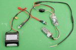
DSC_0739 (1).jpg

This is my first experience of radio control for a model train. For the benefit of anyone else for whom this is completely new, clockwise from the bottom left:
  • battery pack
  • self-resetting fuse
  • charging socket
  • changeover switch (charge/run)
  • controller (with two wires, blue and yellow, to connect to the motor)
  • radio receiver (with built-in aerial)
The kit also comes with a hand-held controller (a radio transmitter) and a charger, I included these in my previous photo of the kit (post no.354).

The batteries are AAA size, nominally 1.2V each. I have gone for nine instead of ten cells in the battery pack, partly because I know I will never want to run the motor flat out, but mainly because nine cells make up into four cells sitting on top of five, and this makes for a slightly more slender assembly.

The plan is to build the tender as a “power pack” for the loco, in the style I suppose of a Greater Anglia FLIRT. The tender will hold the battery, receiver and controller, and provide two wires to connect to the motor in the loco. The GER used the S23 pattern tender for other locos, so if I am sensible I should be able to re-use the tender with a fresh loco one day.

I have now built the brass body of the tender but I will stop here tonight in case we ought to talk about radio control. This is a 2.4 GHz system and the specification gives a range of 800 metres. Running time on a charge of the batteries might be 6 hours but I have forgotten where I got this figure from.
 

paulc

Western Thunderer
Going back to the North Norfolk Railway for a moment, some days just seem to work out perfectly and on my outward journey I found myself sharing a compartment with a modeller who does 16 mm scale live steam. So by the time we reached Weybourne I had learnt about the basics of radio control and where to buy it. His wife seemed very understanding (although I will always wonder if she had come out for the day to get away from model trains ...) so thank you both if you are reading this.

Later I spoke with Steve Foster (Fosworks) and confirmed that I should be able to squeeze one of his simple (no-sound) radio control kits into the tender.

View attachment 172223

This is my first experience of radio control for a model train. For the benefit of anyone else for whom this is completely new, clockwise from the bottom left:
  • battery pack
  • self-resetting fuse
  • charging socket
  • changeover switch (charge/run)
  • controller (with two wires, blue and yellow, to connect to the motor)
  • radio receiver (with built-in aerial)
The kit also comes with a hand-held controller (a radio transmitter) and a charger, I included these in my previous photo of the kit (post no.354).

The batteries are AAA size, nominally 1.2V each. I have gone for nine instead of ten cells in the battery pack, partly because I know I will never want to run the motor flat out, but mainly because nine cells make up into four cells sitting on top of five, and this makes for a slightly more slender assembly.

The plan is to build the tender as a “power pack” for the loco, in the style I suppose of a Greater Anglia FLIRT. The tender will hold the battery, receiver and controller, and provide two wires to connect to the motor in the loco. The GER used the S23 pattern tender for other locos, so if I am sensible I should be able to re-use the tender with a fresh loco one day.

I have now built the brass body of the tender but I will stop here tonight in case we ought to talk about radio control. This is a 2.4 GHz system and the specification gives a range of 800 metres. Running time on a charge of the batteries might be 6 hours but I have forgotten where I got this figure from.
Hi Richard , this is very interesting. Could you let us know the part numbers for the parts in the photo or was it a kit as i know you can buy from Fosworks either way .
 

Richard Gawler

Western Thunderer
Hi Richard , this is very interesting. Could you let us know the part numbers for the parts in the photo or was it a kit as i know you can buy from Fosworks either way .
I bought the equipment as a kit because this way I made sure I had all the parts I needed. Steve discussed my requirements over the phone and suggested the items which seemed the best choice.

These are the parts I bought:
  • BAT AAA 9 cell (custom-made)
  • PNP-120 No.1 loom with micro toggle
  • ESC-161 Cobra speed controller
  • FRx22H Omni receiver
  • PNP-251 Reinforced tender to loco [this is a 2-way connector, I can't see it on the web site]
  • TX 2.0 Omni handset
  • CHG440 Smart charger for 4 to 10 cells
See Fosworks here and other pages.

So really, it is a "custom-made kit". I suspect I could have found the toggle switch and the charging socket in my parts boxes but those 5.1 mm sockets have a variety of centre pin diameters and it was easier to buy it all in one go than to risk having to add small orders later.

I forgot to order an external aerial. In subsequent correspondence, it seems Steve recommends the internal one (etched onto the pcb of the receiver) if at all possible. This is omni-directional, but the external aerial is uni-directional. I understand, the system will continue to work even when reception is severely compromised; and I will find out how well after everything is inside the tender.
 

Richard Gawler

Western Thunderer
I have been using 145 degree solder for attaching my whitemetal castings. I have got away with it most of the time, though the boiler backhead of Nellie will always be missing one rear corner! It doesn't show when installed in the cab.

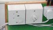
I bought some 70 degree solder ages ago but couldn't work up enough enthusiasm to try it, and yesterday I bought some 100 degree solder. This spurred me on to install a dimmer switch and a 13A socket which I had also bought many months ago.

DSC_0847.jpg
There is a useful upstand on the back of my bench. The socket is rotated to make enough space for the cable leaving the plug but thinking about it now, it might make me stop and think before plugging in anything else e.g. the vacuum cleaner. Power is from the 13A plug to the right.

The dimmer switch is a 400 watt one, ample for any soldering iron I will ever have.
I put a pen mark on the knob.
Twelve-o'clock is good for 100 degree solder, ten o'clock for 70 degree, and four o'clock (maximum) for 145 and 188.

As happens so often, the job took barely an hour to build and I have been looking at the parts, just plonked down on the floor, for months.
 
Last edited:
. . S23 tender and radio control

Richard Gawler

Western Thunderer
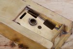
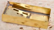
The tender has been designed to build up into two subassemblies, a body and a chassis. I have decided to build mine as three – body, floor with sideframes and buffing gear, and chassis. This will let me dismantle the model afterwards to reach the r/c equipment inside.

DSC_0773.jpg
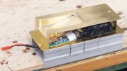
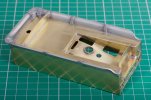
The r/c equipment will pretty much fill the inside of the tender.

DSC_0772.jpg
I have decided to keep the coal space so the loco can run with a small load of coal in the tender. To do this I raised the location of coal floor to make space for the two circuit boards and their wiring. The floor is at the scale position at the front (but see my next post!), then slopes upwards to leave just enough space to cover it with some coal. So the top of the tender can stay clear for toolboxes and the fireman's tools.

DSC_0780.jpg
The charging socket and the toggle switch will tuck down between the two circuit boards. The controller is wider than the receiver, so the two holes are off-centre.

DSC_0785.jpg
I cut some holes to let the radio waves reach the receiver, and then fixed on the wrapper for the sides.

I made a sort of a collar to raise the charging socket, the idea is to let the coal sit around the socket but not inside it.

At this point I made a mistake - the top of the tender ought to be a millimetre or so below the tops of the sides and not flush with them. This has come about because I am building the body upside-down without its floor and without two internal bulkheads. All of these would have set the top at its proper height.

DSC_0804.jpg
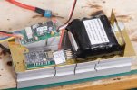
I made a new “floor” to make a compartment for the battery pack. The floor adds some of the rigidity lost by omitting the two bulkheads.

The floor is sloping to make it possible to slide the battery pack in and out. The clearance is a bit tight, so I suspect setting the top too high has been fortuitous.

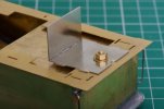
The nut is to hold a screw passing up through the chassis and the floor to hold the tender together. I suspect the nut should be on the inside here (stronger when the screw tightens) but I wanted to leave the battery compartment clear of inivisible obstructions which might chafe into the battery pack.

DSC_0803.jpg
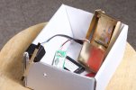
The r/c system has a claimed range of 800 metres but this will be degraded by having the receiver inside the brass tender. I put the receiver inside the battery space to give it some electrical screening and took the system outdoors to do a range test. The motor has a strip of wood attached so I could see operation from a distance.

Using binoculars I could take the transmitter about 60 metres from the system and still confirm operation. There was no evidence of hesitation and the practical range may well be a great deal more, but 60 metres is far more than I will want for operation even on a garden railway so this looks promising.
 
Last edited:

Richard Gawler

Western Thunderer
DSC_0783.jpg
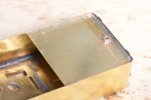
The incorrect alignment of the top of the body left me with a gap at the front of the tender, this is just visible at the top-left corner here.
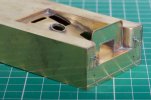
DSC_0835.jpg
I thought of laminating on a complete new front but to be honest most of the problem will be hidden by a hinged flap to go on here. So I soldered on a strip of fret instead to hide the gap. Then the doors and handles for tool compartments.

I emphasise, there is nothing wrong with the kit. The body assembly would have gone together perfectly if I had built it on its base, as its designer intended it to be.
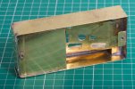
DSC_0836.jpg
I made and added a bracket to hold the fixing nut for the front of the body. Again, the idea is the fixing screw will go through the chassis and then the floor and into the body.

This left me to add the copings. These are three whitemetal castings.
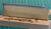
DSC_0845.jpg
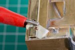
I had to begin by shaving the 1 mm flanges off the bottom of each casting, because I had set the tender top 1mm too high.

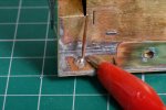
Attaching the first coping then took me most of an hour. I tacked it into place and removed it twice before I decided to accept it at the third attempt. This was my first go with the 100 degree solder – I did a few practice runs with gash castings but of course doing it for real is a lot harder. I still tinned the body with 145 degree solder, I don’t think this did any harm.
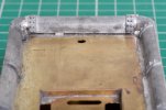
DSC_0850.jpg
The second coping (on the right here) took nearer ten minutes, and then the third one slotted in at the end.
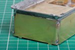
DSC_0858.jpg
There is a gap here, but it's not as bad as it looks. I tweaked the short (end) casting a few times with fingers and pliers, and then accepted the job for what it is.
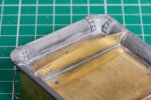
DSC_0862.jpg
The result looked fine (to me!!) on the inside but the back looked skewed.

The vernier calipers confirmed, one end of the short casting (and its adjacent long casting) was about 0.5 mm higher than the other end. So I took out the round-nosed pliers and teased the high end downwards. The difference is now nearer 0.2 mm.

For some reason, 0.5 mm stuck out like a sore thumb but 0.2 mm doesn't notice, however long I stare at it. I guess other viewers will be about the same as me, or a bit more critical or a bit less. This error is across a width of 50 mm or so.
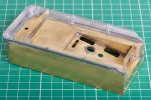
DSC_0863.jpg
So the body of the tender is now pretty much done. I have ordered up a set of miniature "radial bristle abrasive brushes" to help with the clean up, thanks to @Rob Pulham for the tip.

I have no idea how to unsolder castings fixed with 100 degree solder. I suppose the torch would do it, but I would have to ask for three new castings. I think they are there to stay.

So far I have completely overlooked how to arrange the hand rails which go from the front edges of the body onto the floor. This needs some thought :rolleyes:
 
Last edited:

Chas Levin

Western Thunderer
Very nice job overall Richard and very interesting to see experiments with RC.
I sympathise with those feelings when something hasn't quite turned out the way you'd hoped (completely lost count of how many times I've felt that way about just the current project!) but in this case, I think those WM castings will look absolutely fine under primer, coal, coal irons and so forth.
I also find that something bothers me after finishing it almost to the point of losing sleep over it, but a surprisingly short time afterwards, I have to think carefully to remember where on the model the offending place actually was...!
 

Richard Gawler

Western Thunderer
I have just undone one of my 100C test pieces using a candle. The effect was almost instant and didn't melt the casting.

I have only kitchen equipment for boiling water over a sustained period and I feel, on this occasion, I don't want lead and cadmium and whatever else in my next bedtime drink. So I haven't tried the boiling water.
 

Richard Gawler

Western Thunderer
Very nice job overall Richard and very interesting to see experiments with RC.
I sympathise with those feelings when something hasn't quite turned out the way you'd hoped (completely lost count of how many times I've felt that way about just the current project!) but in this case, I think those WM castings will look absolutely fine under primer, coal, coal irons and so forth.
I also find that something bothers me after finishing it almost to the point of losing sleep over it, but a surprisingly short time afterwards, I have to think carefully to remember where on the model the offending place actually was...!

The same happens with me. When I took Nellie to the club track last month, she ran happily for a while and then stopped dead. One of the Slater's wheel hub screws had worked loose and the wheel came adrift. I went to sleep wondering what I could possibly do because I had already over-tightened one of the other wheel screws and it won't budge. In the morning I tightened the loose screw and a month later (last Saturday) she ran fine, no problems. I have forgotten which one is the stuck screw and which one is the re-tightened screw.

The perfectionist in my has now homed in on one of her sets of cab steps, which is just enough out of true for me to notice, but many months on after I built the model.

Realistically, the top of the tender ought to be a very matt and dirty sooty colour and I suspect, the most important thing will be to have nice neat joint lines. I have found a miniature wire brush in the box with my Minicraft drill and this brush seems to clean up soldered "crease" lines rather well. A lot easier and quicker than scraping backwards and forwards with a clogged-up needle file.
 

Ian@StEnochs

Western Thunderer
Richard,
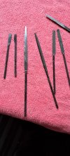
Instead of scraping with a clogged old file why not convert it into a proper solder scraper to easily remove solder. Here are a selection of mine made by grinding off the tèeth and putting a slightly beveled edge on the end. You can remove the teeth with a grindstone, or slitting disc, and once done easy to keep keen with a rub on an oilstone. Even cheap files work and can be custom ground for awkward corners.
Ian20221013_110042.jpg
 

simond

Western Thunderer
Whilst I quite like the music, I'm not keen on heavy metal drinks either, so I put the item in the sink and pour the water out of the kettle over it!
 

Richard Gawler

Western Thunderer
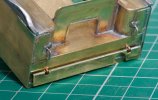
The tender now has a hinged fall plate at the front. This is my second attempt at attaching it . . .

DSC_0873.jpg
A scrap of paper with a drop of oil in it, placed to stop the solder flowing through into the pivot.

DSC_0874.jpg
Split pin soldered up from the inside.

DSC_0878.jpg
Working pivot.

. . . my first attempt, without the bit of paper, was a graphic demonstration of how solder takes to copper (the split pin) and to nickel silver (the pivot rod) better than it takes to brass (where it was wanted). It was too pitiful to take a photo :oops:
 

Rob Pulham

Western Thunderer
Hi Richard,

Just looing at your post re the nut on the bottom of the tender rather than inside and I have a small suggestion if it's not too late. Where you have put the nut on the outside to save having something protruding inside to interfere with the battery. Can I suggest that you put a screw in from the top and use the nut to secure it rather than the other way around. I say this because I had solder a nut into the rear of the cab floor on the J6 as the rear body fastening and although it was on the inside and couldn't be pulled off (as yours might over time) it still came adrift after taking the body on and off multiple times while testing it prior to delivery. I had to make an elaborate bush to get around this as I couldn't get in under the floor to re-solder the nut and I had already done the paint job so needed to make the minimum amount of mess. In future I plan to put screws in from the top and use the nuts from the bottom on all my builds.
 

Richard Gawler

Western Thunderer
Hi Richard,

Just looing at your post re the nut on the bottom of the tender rather than inside and I have a small suggestion if it's not too late. Where you have put the nut on the outside to save having something protruding inside to interfere with the battery. Can I suggest that you put a screw in from the top and use the nut to secure it rather than the other way around. I say this because I had solder a nut into the rear of the cab floor on the J6 as the rear body fastening and although it was on the inside and couldn't be pulled off (as yours might over time) it still came adrift after taking the body on and off multiple times while testing it prior to delivery. I had to make an elaborate bush to get around this as I couldn't get in under the floor to re-solder the nut and I had already done the paint job so needed to make the minimum amount of mess. In future I plan to put screws in from the top and use the nuts from the bottom on all my builds.
Thanks Rob, this is important. Nellie the crane tank has two nuts soldered onto the top surface of her footplate, there is one below the crane which I could get at if it ever came adrift but the one inside the smokebox is sealed in for ever.

The half-nut below my battery compartment would be easier to solder back on if it pulled off, but easier doesn't mean easy if the model has been painted.

DSC_0879.jpg
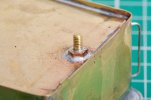
I cannot get my fingers or even tweezers inside the battery compartment to manipulate a screw. So what I have done is open up the hole for the tank filler in the top of the tank to make it large enough to pass the screw through, and inserted the screw from above. There will be a sacrificial scrap of Blue-tack in the slot of the head forever, this held the screw onto the screwdriver. Then I soldered up the thread so the screw cannot work loose.

So I reckon,
Nut = belt
Screw = braces
Solder on thread = string

This is never going to come out, unless I suppose I drill it out.

DSC_0884.jpg
I have ended up with enough thread to pass through the footplate, a chassis spacer, a washer and a nut, and leave most of two full threads showing.

I will have to buy myself a 6BA nut spinner to manipulate this nut after I have built the chassis.

Doing this I have lost the use of the last few mm of battery compartment because the battery pack won't pass beyond the head of the screw. However I can live with this, there is still enough room for the various r/c parts and their wiring.
 
Last edited:

Richard Gawler

Western Thunderer
Richard,
Instead of scraping with a clogged old file why not convert it into a proper solder scraper to easily remove solder. Here are a selection of mine made by grinding off the tèeth and putting a slightly beveled edge on the end. You can remove the teeth with a grindstone, or slitting disc, and once done easy to keep keen with a rub on an oilstone. Even cheap files work and can be custom ground for awkward corners.
Ian

Ian, the reason for not making a solder scraper was I never realised a slitting disc would go through a needle file! Having done this I have made a scraper using the handle and the first part of the file, and I have worked my way around the nooks and crannies on my tender.

DSC_0892 (2).jpg
Then I got out a bit of wire wool to finish it off.

I have pulled off the two rear handrails because I have already knocked them twice. I will put new ones on nearer the end of the project.
 
Top