The Heybridge Railway, 1889 to 1913

simond

Western Thunderer
Richard,

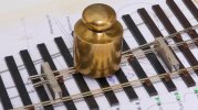
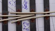
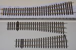
I build my vees like the one on the left of your photo (hopefully with straight transitions from wing rails and even flangeways!) so that the strips of 1mm brass that join the parts together coincide with the timbers. Cosmetic half chairs are glued on later.

I’m a strong believer in “function before form” :)
 

Richard Gawler

Western Thunderer
Simon,

I probably spent far too long thinking about this but I ended up using the little patch of brass because it would give me something substantial to glue down onto two adjacent timbers (with styrene shims to set the height); and if the crossing assembly was not quite flat from end to end I ought to be able to ease it flat without breaking it apart! I will lose daylight between these two timbers, but on the bright side I won't have ballast working its way upwards into the flangeways.
 

Dog Star

Western Thunderer
Richard,

There are those who consider that I am a pedant in regard to S&W practice and in general those peeps may be correct. In the past I have followed Simon's approach in respect of brass strips and cosmetic chairs, nothing wrong with that approach at all. When I have built 2mm track then my approach to constructing the common crossing has been very much in line with your approach and for much the same reasons - especially so as to get a "flat" crossing.

Maybe your approach offers a more secure dose of "function", building crossings in your style is going to stand you well when you come to operating your layout.

regards, Graham
 

Richard Gawler

Western Thunderer
Maybe your approach offers a more secure dose of "function", building crossings in your style is going to stand you well when you come to operating your layout.
Graham your post has come at a perfect time because I can upload some photos of the finished crossing and its surrounding rails and spare everyone the steps I took along the way.

DSC_0603.jpg
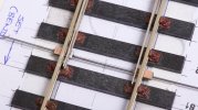
I ended up with a shim of 0.5 mm styrene to raise the crossing to reach the tops of the first stock rail. So superglue for the brass/styrene connection and Butanone for the styrene/ABS connection.

DSC_0629.jpg
A mate has some Heljan diesels. I don't even know whether these will run through 0-MF, I have read about them having a non-standard wheel profile. Anyway, I have a fear of a kilo+ of derailed class 40 hitting the crossing at speed. So for robustness, this is my best effort without embedding everything here in Araldite of similar.

DSC_0632.jpg
The piece of brass is just about visible at a normal viewing angle but it doesn't bother me and I would hope there will be something more interesting on the layout to divert attention away from it. (The layout is not designed yet).

There is a story behind the red mark. The bullhead rail supplied with the kit is a "true bullhead" profile, not a "flat-bottomed bullhead" as used in Peco track. I had the first switch blade upside down when I cut it to length, so this blade ended up on the opposite side of the track and about 1 mm too short. The second switch blade had planing on both sides (though more on one side than the other) and the red mark is there to show me the top.

I used Peco rail for the two stock rails so I have ended up with a turnout with two different rail profiles and I imagine needing two sorts of rail joiner to connect it to other track.
 
Last edited:

Richard Gawler

Western Thunderer
DSC_0636.jpg
This is my take on a mildly flexible tiebar, this might stay put longer than a strip of copperclad.

I found the idea for using pieces of double-sided copperclad in an article by Jim Snowdon in the GOG Gazette. The copperclad is pieces cut from a 4mm scale sleeper. They stop the point blades working their way upwards, and soldering the tiebar underneath gives the necessary insulation. The bar itself is piano wire, the original post suggested using phosphor bronze which I don't have. I forgot to dress the insides of the stock rails and the slight untidiness is a touch from the mini grinding disc.

The two stock rails are tending to lift off the timbers here. When the point goes onto a baseboard I can put in a few brass pins to hold the rails down. This is my B6 completed until it goes onto a baseboard.
 
Last edited:

Richard Gawler

Western Thunderer
DSC_0639.jpg
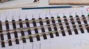
A quick comparison of my curved B6 (top) with my Marcway 6ft and 4ft radius points in case this is useful to anyone planning their first 0 gauge layout. The 6ft point is very close to the geometry of an A5, but the arrangement of the wing rails and check rails is peculiar and I want to rebuild these. I could have sorted these out the first time round if I had been paying attention.

The sharp-eyed will notice the B6 is now on a fresh template. I have learnt the hard way, do not ever try to take one of these constructions off its paper template. If you do, all of the timbers with slide chairs will fall off and the whole assembly will assume the shape of a straight point :'(

And you will have to reprint an identical template to rebuild it onto as well.

My new template is glued onto a sheet of 1.5 mm mount board, so this part of my trackwork is going to be 1.5 mm higher than it might have been. The mount board had just enough flexibility to let me rest the heel end of the template onto a book, lift the toe end into mid air, and work my way from the crossing back to the tiebar. Never again.
 

simond

Western Thunderer
Been there, done that.

I now stick my Templot templates to a piece of card (greyboard, like cornflake packet material) with PVA, and tape the assembly to a spare bit of contiboard, and build on that.
 

Richard Gawler

Western Thunderer
Been there, done that.

I have learnt about different rail sections at the weekend, and I suspect using Peco slide chairs for Peco rail (instead of the C&L chairs from the kit) would have made for a stronger job.

- -

I will have to build the track for my “Heybridge Railway” because I want 9 ft sleepers and pointwork to match, and I want the points to at least resemble scale models accepting the distortions of the 32 and 31.5 mm gauges.

Until last weekend, I thought of the railway as being laid with lightweight FB rail and I had bought a packet of spikes to do this. Last Sunday I went to the Bury St Edmunds show (excellent!) and I was able to inspect some true 7mm scale FB rail. This made me realise, Peco code 100 FB rail would be too narrow while their spikes are overscale.

In the meantime, I have accumulated eight yards of Peco BH Streamline track. Three bought new to create my test track and five gifted from the mate who sent me his unwanted point kit.

So I have decided to make the most of what I have including my completed B6 and the Peco rail and today I bought the Peco chairs to build the rest of the track. The shop assistant remarked that I was the first person to ask for Individulay in living memory and offered some in packets dating from when Peco chairs had “SL” not “IL” part numbers. 350 chairs for £4 can’t be bad; support your local model shop I say :)
 

Richard Gawler

Western Thunderer
Screenshot 2022-09-21 11.42.53.png

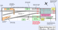
This seems like a good time to post up my present thoughts on a layout. I would like to build this next year, when the weather is warm enough again to do the carpentry outdoors, and when I am sure I am building the right thing. I have a few ideas for layout designs but this is the only one small enough to fit into my hobby room without dismantling my 16.5 mm gauge layout, which I would like to keep.

The design draws heavily on the work of @Jim Read and his micro layouts on his YouTube channel '7mm micro'. The main change I have made is to use much larger points. I am fairly happy with the arrangements here in the horizontal plane but the gradients and levels need work. I have ideas on having the tracks into the fiddle yard on two levels ('high' and 'low') with the traverser able to move up and down . . . I can imagine this traverser becoming a mini-project in its own right so I started a separate thread for it, see https://www.westernthunder.co.uk/th...h-added-vertical-movements.10974/#post-259149.

I want to use gravity to work passenger trains. In broad terms, a loco draws its one-coach train from the fiddle yard into the passenger platform and this road is slightly downhill. The passengers alight and the loco propels the coach back towards the fiddle yard. The "guard" applies a brake on the coach (I guess a servo moves a prong upwards in front of an axle), and then the loco uncouples and runs into the spur. The guard lets the coach roll back into the platform and the loco runs round to the other end of its train.

I guess I need to build the coach to find out how well it runs and how steep the gradient needs to be!

But I welcome any thoughts on the practicality of otherwise of this layout design; it is I think my 17th layout (in the last 52 years!) but my first in 7mm scale. I want it primarily as a test track and for photography at home, and for operations if it can go to a show. There is room for expansion to the left, taking the line towards Heybridge Basin by running on a lid on top of my 16.5 mm fiddle yard.

Edit: I have set this up full size with odd bits of track on a length of wallpaper, so I know roughly how well the track will fit. The two points will be slightly curved because this looks better, but AnyRail doesn't support custom trackwork so the plan shows best-fit items from C&L. I might end up taking the width of the boards up to 550 mm.
 
Last edited:

Richard Gawler

Western Thunderer
The second point for this scheme (the one by the goods shed) is going to be an A-6. I chanced upon a copperclad kit for one of these by Waverley Models, picked up for £15 at the Bury St Edmunds show. Construction is using the vee, wing rails, check rails and point blades from the kit, with new longer stock rails using Peco rail. The timbers are Peco plus a few C&L ones from the B-6 I did earlier, and chairs are a mixture of C&L, Kalgarin/Permaway and Peco to suit the different rail sections.

I have decided to standardise on Peco BH rail for the rest of the layout because I can buy it from multiple sources, and the chairs to suit as well. So there will be "true bullhead" rail on the insides of the two points, and "Peco FB bullhead" on the outsides and on the plain line.

DSC_0656.jpg
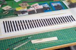
Timbers fixed with double-sided tape onto template, this fixed with spray-mount onto 1.5 mm mount board, and this taped onto a bit of chipboard. Straw board suggested by @simond would be more economical but all of my pieces are too small.

If this works out ok it will have been a very economical construction because I have ended up with just one usable offcut from the bag of Peco timbers and I had used some of these earlier for the B-6.

I put a slight right-hand curve on the template. Just enough to take away the "straight look" of a ready-made point but without increasing the length much. The minimum running radius is now down to 66 inches, so when this is built it will become my new test track for 6-wheeled chassis. Hopefully they will run without needing much extra sideplay.

If I am blessed, this will be the last point I have to build for a few years. The writer of some kit instructions described the process as "therapeutic" . . . possibly therapy for his bank balance. It is more "necessary but dull" to me.
 
Last edited:

Richard Gawler

Western Thunderer
So, the cosmetic trimming around the check rails gets half a Peco chair on the outside and half a Permaway chair on the inside. They are moulded in identical shades of brown and this shade matches the shade of the timbers perfectly :headbang:

I have two desk lamps immediately above the work.
 
Last edited:

Richard Gawler

Western Thunderer
I have completed my A-6 as far as I can take it before installation onto a layout and wiring it up. I have realised, all the plain track is going to have to be hand-made (so I can have pre-grouping sleepers) so this one is 31.5 mm gauge throughout. Here are some photos with notes to record my thoughts along the way.
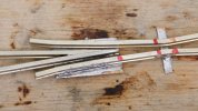
DSC_0658 (1).jpg
I think this is how a vee should be built. The rails were shaped and soldered together by Waverley Models. I have given their vee a blunt nose and a little curvature on the top. Looking at the wing rails, I can do neater soldering than this but speed was important to make sure the vee stayed intact.

I am happy with broad alignment marks from the red Sharpie. I know whether I am aiming for the middle or one end of a mark. This crossing is a bit tighter than my last attempt in that the feeler gauges are a light interference fit not a clearance fit in the flangeways.
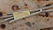
DSC_0661 (1).jpg
The brass plate gives a reasonably large surface area to glue the crossing down onto the timbers.
DSC_0665 (1).jpg
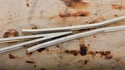
This is the crossing after scrubbing with Cif stainless steel cleaner but before final cleaning up.
DSC_0667 (1).jpg
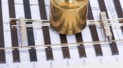
There is a 0.5 mm styrene shim between the timbers and the crossing. The shim has cyano on its top surface and Butanone on its underneath. 500 grams left here for an hour while I had breakfast.

I have missed out some chairs on the stock rail here to make room for full chairs to hold the check rail. The Peco timbers are hollow underneath but their inverted U section will be hidden by ballast.
DSC_0670 (1).jpg
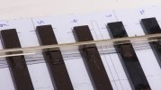
This is Peco BH style rail, I have filed away the foot of the rail to help the blade to sit flush. The slide chairs are Kalgarin/Permaway. Peco make these as well but they seem too long to me.
DSC_0672 (1).jpg
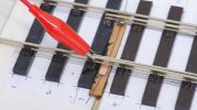
Most of the battle with awkward soldering is making a temporary fixture to hold everything in place. Offcut of rail bent into a shallow elbow and jammed under a spare copperclad sleeper. Croc clip is gentle but enough.

This time I am trying 0.4 mm piano wire for the tiebar. It doesn’t seem very strong but it is stronger than the solder joints at each end. The scraps of copperclad at each end are from an idea by Jim Snowdon published in the GOG Gazette, they keep the tops of the blades in line with the tops of the stock rails.
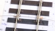

DSC_0674 (1).jpg
I have read somewhere, the blades should settle to a neutral position mid-way. I don’t know why this is needed but I seem to have achieved it here.
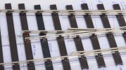
DSC_0677 (1).jpg
These chairs are a mix of C&L (light brown), Peco (foreground) and Permaway (middle and top).
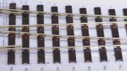
DSC_0678 (1).jpg
The kit provided long wing rails and short point blades. This was going to put the insulated gaps in an unconventional location. I decided to cut new gaps in the usual place and solder the blades end onto the wing rails. I am hoping this "workmanship" will disappear with some Araldite in the gaps and a few coats of paint especially over the solder. There is something scary about soldering so close to ABS.
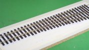
DSC_0684 (1).jpg
If 0 gauge is 32 mm gauge and 0-SF is 31 mm gauge, the 0-MF as I have aimed for here is probably a safe bet for me because small errors either side of the nominal 31.5 mm should leave the gauge within the extremes of what I consider to be the sloppiest and tightest standards and all of my stock will run. The flangeway gaps are much the same as those on a Peco Setrack point for H0, half the linear scale, which might be food for thought.

I can feel a tiny wheel drop with Slater’s wagon wheels but I cannot see it. If the crossing was 1:5 instead of 1:6 there wouldn’t be any wheel drop at all.

I can put this all away now, knowing the points are ready when I come to build a layout.
 
Last edited:
GWR Hydra (1908) . . part 2 paint and couplings

Richard Gawler

Western Thunderer
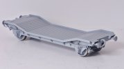
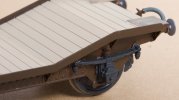
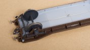
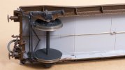
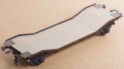
I have had a go at finishing off my GWR Hydra. It still needs transfers but it does have paint and couplings. This has taken me four months since I did the primer.
DSC_9583.jpg
My last post on the model is here: The Heybridge Railway, 1889 to 1913

DSC_0376.jpg
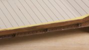
I brush painted the timber decking with a Mig acrylic and this covered in two coats.

DSC_0703.jpg
I brush painted the frames in Railmatch enamel ("GWR Stock Brown") and three coats weren't enough.

I thought brush painting would be easy and indeed quicker than masking up for spraying but to be honest it took over a week. Three coats on each of the four sides with each coat left overnight to dry. I am not good enough at painting to say what has gone wrong, but I am sure the enamels I bought twenty years ago brushed on more easily and covered better. Especially dark browns.

DSC_0699.jpg
I did the tread plates with acrylics to try to represent worn steel. They look better on the model that they do here.

DSC_0722.jpg
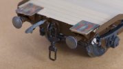
I was never happy with the short lengths of tube on the couplings and I re-did them with a wire link. I couldn't get my fingers into the spaces to fit the springs and split pins, and soldering on the hooks from the outside would have needed a re-paint.

DSC_0727.jpg
The coupling hooks are loose in the headstocks and the wire is as taut as I can make it. I guess it will eventually stretch and I wll have to re-work things but I have been able to do a test run and the wagon runs fine through my Setrack point, both legs in both directions.

DSC_0702.jpg
The bottom line here is, I am pleased with my model but not my painting . . . and I suspect everything would look a whole lot better with a suitable load.
 
GER Y14 (1891)

Richard Gawler

Western Thunderer
GER Y14 Project for Winter 2022-2023

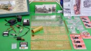
Back in the summer I bought myself a Connoisseur Models kit for a LNER J15; and building this up as a GER Y14 is going to be my project for the winter.

My imaginary Heybridge Railway is a short branch off the former Witham to Maldon branch and some members of the class worked the line in BR days. Going back to the 1890s, I don’t have any photographic evidence but I would like to think the Great Eastern Railway operated the locomotives on the line back then. The Y14 had a very good route availability (RA 1) so it could work across the timber viaducts near Wickham Bishops.

I doubt I will ever have room for a home layout large enough to let an 0 gauge locomotive run at any speed or over much distance but I do have access to the club test track, two and possibly three garden railways, and the layouts at another club. These are all sociable places and, well, I want to have a mid-size loco of my own to take along to haul my wagons and my friend’s trains. These friends and others have variously opted for two-rail, three-rail, stud contact, analogue and digital command control (!) . . . .and so a dead-track loco using battery power and radio control seems like a good idea for me. I can take along my loco and its own controller and it should be able to run on any 0-F or 0-MF trackwork. "Only clockwork could be easier".

(As an aside, this also means for my Heybridge Railway there is a separate controller for through workings by the GER).

DSC_0747 (1).jpg
I have cleared my bench and this photo is my version of an unboxing video for WT.

This lot ought to keep me out of mischief for a while?
 

Richard Gawler

Western Thunderer
P1040393.jpg
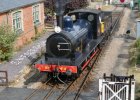
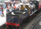
On 23rd August I took a day trip to the North Norfolk Railway to see the preserved J15, built in 1912. The idea was to go to Weybourne and blag my way into the shed and take some detail photos of the lady, but lo and behold there she was in steam and waiting at Sheringham when I arrived. So I got a stack of photos and all of them in good daylight.

The locomotive is currently running with her original GER number 564 and been cosmetically altered to look like a locomotive from an earlier batch. The tender is of a late design, and I suspect that the combination of locomotive and tender on show does not represent any locomotive as it was when it entered service. I remind myself, steam railways do ‘preservation’ not ‘conservation’, and preservation has no bounds on alterations.

The GER built 289 Y14s from 1883 to 1913, with plenty of variations along the way. The Connoisseur kit builds into an example from the final batch (1913), much too late for me. Fortunately, I have some extensive notes from the Great Eastern Society and I have read enough of them to be able to see through the variations and discrepancies on 564 and choose my batch of source loco:

(1) The kit gives me a GER S23 pattern tender, and the first locos with this tender were built in 1889/90. This gives me an entry point. These tenders had frames with D-shaped slots, and the locos had a flat grate boiler. The kit provides sausage-shaped slots and a sloped grate boiler.

(2) The GER used the D-shaped slots until 1899 when they switched to the sausage-shaped slots. This is too late for me, so I need to make some new frames for the tender.

(3) If I cannot work out how to represent a flat grate boiler then I can make a model of a slightly later loco (1891/2 build) with a sloped grate boiler.

The possible batches for my project are, therefore, the following:
  • R23, T23, Y23 (1889) and U25, Y25 (1990) all with a flat grate boiler
  • L28, N28, P28 (1891) and S28 (1891-2), X28 (1892) all with a sloping grate boiler
I don’t need to replicate an exact locomotive, and I suspect it will be a bit over-ambitious to seek out photographs of specific locomotives. If I can represent a typical example from one of these batches, I will be happy.

This will be a freight locomotive with a brake on the tender, no brakes on the loco and no train brake. The tender will not have a tool rack. I like the sound of this – less detail to get wrong.

P1040390.jpg
I need to find out about the security chains each side of the screw coupling on 564. The cab will have a low roof with deep side windows (like 564), and these features are supported by the kit. I have one hundred prototypes to choose from, ten per batch.
 
Last edited:

Phil O

Western Thunderer
Look along the bottom of the firebox, if the bottom is level, that will be a flat grate, if it's deeper at the front, then it will be a sloping grate. The question is did they extend the front down or reduce the rear, to create the slope.
 

Richard Gawler

Western Thunderer
Look along the bottom of the firebox, if the bottom is level, that will be a flat grate, if it's deeper at the front, then it will be a sloping grate. The question is did they extend the front down or reduce the rear, to create the slope.

I photographed the preserved J15 before I saw the drawings and historical notes from the GERS . . . and in spite of taking over fifty photographs, I completely ignored the bottom of the firebox!

DSC_0808.jpg
The etch includes the detail of the firebox stays, represented pictorially I suppose as part of the frame. This is representing a 1913 loco with a sloping grate. I guess, the lowest part of the grate was above the bottom of the frames so it cannot be seen from the side.

DSC_0810.jpg
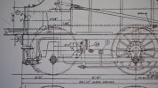
GERS drawing number L39 shows the frames of a loco with a flat grate, and also the outline of the firebox behind. (This drawing is copyright of the Great Eastern Society and I have reproduced a small part here for study and illustration. My reproduction is distorted vertically).

It seems to me, I could go to the frame etches with a piercing saw and cut out the earlier profile, then fill in or obscure the etched firebox detail, and then add some sheet brass inside to represent the flat grate. Whether this is sensible for me to try is another matter!

What I am lacking is any real knowledge of the prototypes, either by looking at the preserved loco or old photographs. So if anyone can tell me whether they know drawing L39 or indeed the frame etches are true to their respective prototypes, this would be a great help. Pun not really intended but seems appropriate.
 

Phil O

Western Thunderer
Looking at that drawing, the grate is level. Part 5 looks like a blow down valve and a mud hole door just behind it.
 

Richard Gawler

Western Thunderer
Looking at that drawing, the grate is level. Part 5 looks like a blow down valve and a mud hole door just behind it.
This sounds like enough to persuade me to alter the frames. I can cut pieces of brass to slip in behind to represent the firebox and drill holes for the valve and door. The frame detail near here is going to be a bit sketchy because there is a motor and gearbox nearby, but I think the rework will be worthwhile.
 
Last edited:
Top