You are using an out of date browser. It may not display this or other websites correctly.
You should upgrade or use an alternative browser.
You should upgrade or use an alternative browser.
Threadmarks
View all 124 threadmarks
Reader mode
Reader mode
Recent threadmarks
LT&SR horse box (1878) . . part 1 unboxing LT&SR horse box (1878) . . part 2 solebars ends and sides ( Diversion : sixteen wagons at NEEGOG ) GER C53 (1903 onwards) The Beast of Heybridge ( Diversion : 'Lady Marion' with train, SM32 garden railway ) New LT&SR horse box (1878) . . part 3 using solder paste and a RSU New LT&SR horse box (1878) . . part 4 RSU probe rebuild NewRichardG
Western Thunderer
Well, for the record I can own up to building seven turnouts. The first five were copperclad ones for 16.2 mm gauge; of these the second was a failure and the other four actually came out pretty well. But the two here for 7mm scale are my first with chairs. For me, I think it will be best to build the common crossings onto pieces of sheet brass so I have a subassembly I can lay onto the timbers and, as Dave says, work outwards from there.
Osgood
Western Thunderer
Spotted this yesterday in a film and thought I should take heed of it:Richard,
I think this is your second turnout, and I think you can be quite happy with it. It’s a learning curve.
think of it thus
a good landing is one you walk away from. A great landing is one after which you can still use the plane.

RichardG
Western Thunderer
Ken I saw their track bases at the show, they looked nicely made . . . do tell us how you get on with them.I bought a greenwood kit at guildford they don't seem to bad a kit, cheap to
I have a stash of Peco parts to build my next turnout (at least when I can decide on the template) but seeing how we get on with the other offerings from the Trade has got to be useful to know.
Last edited:
RichardG
Western Thunderer
Trial runs on the club track, and temporary shims
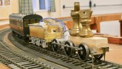
The chassis ran happily on the club track, this is a demountable oval with Peco large radius points. The track is not quite level (like the floor I guess!) and haulage with 8 + 4 oz weights was limited to two free-running but heavy coaches on the short uphill section and an easy three everywhere else. The chassis spinning its wheels when the load was too much.
Having returned home I disengaged the worm gear from the worm and realised these trial runs have let the chassis bed itself in and really the mechanism feels like silk now. So while I am grateful for the suggestions of a floating gearbox and a slotted axle I want to keep these in mind for future models and limit my changes to adding some shims behind the wheels. The chassis has now run for 2 hours on blocks on the bench and 2+ hours under load on various tracks.
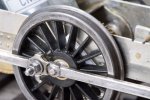
The shim washers haven't arrived so I have added two temporary shims from 0.5 mm styrene onto the middle axle, these are squares of styrene with holes knocked out with a paper punch. So the chassis now has about 0.2 mm free play on all three axles. I have also managed to persuade these two wheels to go a bit further onto their axle so the B2B is now 29.2 to 29.3 mm, one or both wheels is not perfectly true on its axle.
The result is an unweighted chassis which consistently runs round a Setrack curve with an audible flange squeal, consistently derails on my Setrack point (gauge drops towards 31 mm) and runs fine through a Marcway 4 ft radius point. It also runs fine through my A6 point with its "widened timbers". And if the unweighted chassis will do this, it will surely run as well or better with a body and maybe some extra weight to improve haulage capacity. This was the last trial running of the chassis with temporary weights in lieu of a body.

The chassis ran happily on the club track, this is a demountable oval with Peco large radius points. The track is not quite level (like the floor I guess!) and haulage with 8 + 4 oz weights was limited to two free-running but heavy coaches on the short uphill section and an easy three everywhere else. The chassis spinning its wheels when the load was too much.
Having returned home I disengaged the worm gear from the worm and realised these trial runs have let the chassis bed itself in and really the mechanism feels like silk now. So while I am grateful for the suggestions of a floating gearbox and a slotted axle I want to keep these in mind for future models and limit my changes to adding some shims behind the wheels. The chassis has now run for 2 hours on blocks on the bench and 2+ hours under load on various tracks.

The shim washers haven't arrived so I have added two temporary shims from 0.5 mm styrene onto the middle axle, these are squares of styrene with holes knocked out with a paper punch. So the chassis now has about 0.2 mm free play on all three axles. I have also managed to persuade these two wheels to go a bit further onto their axle so the B2B is now 29.2 to 29.3 mm, one or both wheels is not perfectly true on its axle.
The result is an unweighted chassis which consistently runs round a Setrack curve with an audible flange squeal, consistently derails on my Setrack point (gauge drops towards 31 mm) and runs fine through a Marcway 4 ft radius point. It also runs fine through my A6 point with its "widened timbers". And if the unweighted chassis will do this, it will surely run as well or better with a body and maybe some extra weight to improve haulage capacity. This was the last trial running of the chassis with temporary weights in lieu of a body.
Last edited:
. . superstructure and detail parts
RichardG
Western Thunderer
Well I am pleased with my styrene shims even if no-one else approves, and they will do me fine until the metal washers arrive.
I had intended to leave starting the body until the New Year but somehow succumbed to temptation a few days ago. This has not been without incident . . .
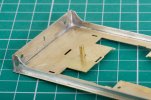
I am using the micro flame torch for most of the soldering, so I am using a lot less solder and not spreading it around to width of the bit so much. Although I did use the iron for the corners of the buffer beam.
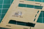
The kit expects you to solder a pair of 6BA nuts onto the top of the footplate and these will accept a pair of machine screws to hold the body onto the chassis. Thanks to a member of WT I have been warned of the problems this can bring about if a nut should ever come adrift after the superstructure is built, so I soldered the screws onto the footplate instead. The nuts will go on from underneath.
I chose 188 degree solder to make a stronger joint, fair enough I suppose but I let the flame linger rather too long, annealed this patch of brass in the process and it promptly sprang upwards into a gentle curve. I have used my fingers to manipulate it back to be "fairly flat" but it is only going to be really flat when the nut is clamping the screw onto the chassis spacer. Something to watch when I try to add the cab sides and the cab floor.
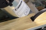
There is hardly any free space for the motor and I filed away a couple of corners of the footplate to clear the motor can. So really, a floating gearbox does need to be designed into the build before starting assembly. I truly thought I had removed all of the cusps and there is one staring me in the face in this photo.
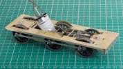
So this is what I have so far.
The shadow between the footplate and the frame spacer behind the motor exists because this spacer sits lower than the spacer behind it. The distortion of the footplate is not as bad as it looks.
I had intended to leave starting the body until the New Year but somehow succumbed to temptation a few days ago. This has not been without incident . . .

I am using the micro flame torch for most of the soldering, so I am using a lot less solder and not spreading it around to width of the bit so much. Although I did use the iron for the corners of the buffer beam.

The kit expects you to solder a pair of 6BA nuts onto the top of the footplate and these will accept a pair of machine screws to hold the body onto the chassis. Thanks to a member of WT I have been warned of the problems this can bring about if a nut should ever come adrift after the superstructure is built, so I soldered the screws onto the footplate instead. The nuts will go on from underneath.
I chose 188 degree solder to make a stronger joint, fair enough I suppose but I let the flame linger rather too long, annealed this patch of brass in the process and it promptly sprang upwards into a gentle curve. I have used my fingers to manipulate it back to be "fairly flat" but it is only going to be really flat when the nut is clamping the screw onto the chassis spacer. Something to watch when I try to add the cab sides and the cab floor.

There is hardly any free space for the motor and I filed away a couple of corners of the footplate to clear the motor can. So really, a floating gearbox does need to be designed into the build before starting assembly. I truly thought I had removed all of the cusps and there is one staring me in the face in this photo.

So this is what I have so far.
The shadow between the footplate and the frame spacer behind the motor exists because this spacer sits lower than the spacer behind it. The distortion of the footplate is not as bad as it looks.
simond
Western Thunderer
Nowt wrong with styrene washers as shims. Just make sure that the outside corners can’t bind.
Whilst I can see no reason for a nut coming off inside the model unless it wasn’t soldered on properly to start with, screws from above is a good plan, otherwise solder a bit of thick brass on and tap it. In any case, make sure there’s clearance for the end of the screw.
if you ever do put screws in from below, it may help to solder some bits of brass tube into the chassis to guide the screws in. Saves a lot of fiddling and bad language. I guess the counterpart to that is to make very tall nuts so they are easy to tighten inside the chassis, if the screw is fitted to the body.
atb
Simon
Or (and) file the first few threads off the end of the bolt, using a sacrificial nut as a stop.if you ever do put screws in from below, it may help to solder some bits of brass tube into the chassis to guide the screws in. Saves a lot of fiddling and bad language.
RichardG
Western Thunderer
I guess the counterpart to that is to make very tall nuts so they are easy to tighten inside the chassis, if the screw is fitted to the body.
Years ago (a lot of years ago) a valve radio would include some threaded hexagonal spacers, 4BA or 6BA, and these would be just the thing. I fear I threw mine away when I thought the world was going metric . . . if I cannot find replacements then I will have to buy some box spanners.
Rob Pulham
Western Thunderer
Here you go Richard,
Not box spanners specifically but I have some of these and can recommend them. I made some extra handles for mine so each head except the two I use least (14ba/16ba) has it's own handle.
I fitted the 14ba/16ba heads to each end of a single handle as I don't tend to use them as much. Not being able to get quite the same grip with one on either end, I am not tempted to overtighten and possibly shear them.
BA Nut Spinner
Rob Pulham
Western Thunderer
Every now and then you obtain a tool so useful, that that you rapidly wonder how you ever managed without it. These have become such a go to tool here.
RichardG
Western Thunderer
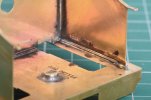
The joints between the sides of the cab and the footplate seemed a bit minimal so I reinforced them with lengths of wire. I don't know whether this will help or even if it is necessary but it is done now.
I washed this work with Cif 'Perfect Finish Stainless Steel' (intended for kitchen sinks), this cleans the job but it makes solder go dark.
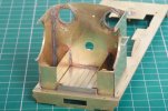
I went back to Viakal for the next rinse. Most of the soldering is with the microflame torch and the result has needed very little cleaning up.
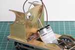
I have been told I will have "no problems at all with this kit". Well, I found assembling the three sides of the cab quite tricky and ended up with a leather glove on one hand while the solder went into the vertical corners. The result is tidy on the outside so having done it I will have to admit it wasn't exactly 'difficult' though I did wish for a fold-up arrangement for a while. The cab sides are parallel to the footplate and the gaps underneath them (about 0.1 mm) will be hidden by some flange pieces to go on later.
michael mott
Western Thunderer
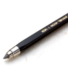
Why did I not think of this before? Thanks for the tip Simon.clutch pencils are a useful way of approaching the smaller BA fasteners
View attachment 176519
this sort of thing. Not for tightening or loosening, but insertion and retrieval...
Michael
simond
Western Thunderer
Richard,
you need the “Simon’s patent cab sheet holder” or whatever I called it on my Garratt thread on RMW.
It’s a block of softwood, about 15mm cube-ish, with two razor-saw cuts at a pretty precise right angle in one face.
Push the top edges of the cab side and spectacle plate into the cuts, arrange the lower edges of said sheets on footplate, apply digit of one hand to top, hold solder between other digits and thumb of same hand, and wield hot-stick with t’other.
it was supposed to make my fortune and let me live in the style to which I’d very much like to become accustomed, but alas, it was not to be. I hope it helps,
Merry Christmas
Simon
RichardG
Western Thunderer
I have sadly come to realise it doesn't work this way. Years ago I suggested a really short live section of crossing vee for pointwork, this was duly dismissed out of hand on the forum and now we have Unifrog. Then again, I should probably accept Peco did actually invent it themselves and weren't reading my posts on a daily basis at the time.it was supposed to make my fortune and let me live in the style to which I’d very much like to become accustomed, but alas, it was not to be. I hope it helps,
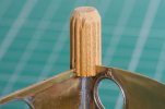
The cab soldering was actually "done" when I posted the last photos but I have made a miniature version of the corner clamp. This let me scrape off some of the surplus solder and then re-flow it knowing the joint would stay in alignment. The clamp is a neat idea. Mine has one slot widened out because the tops of the cab sides are double thickness.
Looking at this photo I suspect I have overdone the solder scraping. I will be happier with the strength of the cab after the roof is soldered on, I will have to cut this out myself because I am deviating from the version of the loco the kit is designed to build.
Threadmarks
View all 124 threadmarks
Reader mode
Reader mode

