The Heybridge Railway, 1889 to 1913

Richard Gawler

Western Thunderer
Smokebox, take 2.

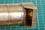
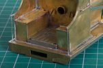
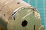
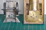
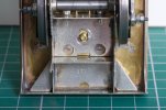
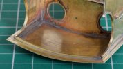
I am posting some new photos for the second smokebox because I deviated from the kit instructions and I found my revised approach was easier.

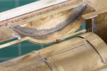
I began by annealing the wrapper to a blue colour, this lets you curve the metal over a former and it will stay put without springing back. (Sorry, I expect everyone else here already knows this!) For me the former was the handle of my micro flame torch.

DSC_1608.jpg
Then I formed the reverse curves and attached the wrapper to the front. This is the easy part done, the only thing to watch is the wrapper must be like the surface or a cylinder not the surface of a cone. Then I filed the locating lugs off one side of both spacers.

DSC_1610.jpg
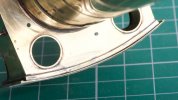
I treated myself to the less scorched side of my bit of plywood and tacked on the two formers.

DSC_1618.jpg
With the lugs removed it is easy to rotate one or both formers to get a good alignment between the back and the wrapper. This photo also shows how the wrapper is holding its shape.

DSC_1621.jpg
I finished soldering the back around the outside, not pretty but it all got filed off later.

DSC_1640.jpg
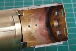
Then I pulled out the two formers and soldered up the back to the wrapper on the inside. The torch made this so much easier.

I did ponder putting the formers back in and soldering them up solid. Then I thought, the cab manages to be strong enough without having internal bracing, and so the smokebox should be able to survive without them too.

DSC_1629.jpg
Cleaned up and suitably posed.

Really, this isn't so difficult if you take your time, you take on board the instructions, and you work in a way in which you feel happy. I do find a woodscrew + washer much easier to use than a drawing pin to hold the work onto the board.
 

Richard Gawler

Western Thunderer
Smokebox / boiler / firebox assembly.
DSC_1604.jpg
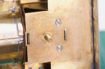
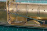
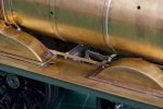
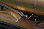
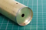
The boiler front supplied has a half-etched flange so it sits concentrically on the front of the boiler. I removed the flange and put the boiler front inside the boiler, this made attaching the (second) smokebox a great deal easier. The boiler was slightly oval and the boiler front is now sprung into place and holding it circular.
DSC_1641.jpg
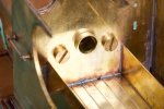
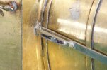
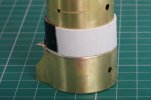
The boiler front and the smokebox front and back have etched holes to assist alignment. These were a loose fit on a 6mm drill bit so I opened them up to a snug 1/4 inch. Unfortunately, the smokebox was still going to end up about 0.1 mm offset to one side, I know this doesn't sound like much but the difference is doubled when you look at the fit around the smokebox. So I abandoned the drill bit and used a strip of 1 mm card to set up the boiler onto the smokebox. The piece of card sliding up the boiler to let me solder the joint.
DSC_1654.jpg
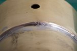
However hard I tried, I had to put a small twist onto the smoke box to get it to look right, see the etched guide marks in the photo.
DSC_1672.jpg
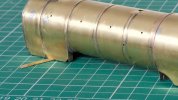
At the end of the day, I am going to have to put a shim about 0.4 mm below this side of the firebox. The whole assembly will then sit flat onto the footplate without pulling it crooked. The shim will be hidden behind a piece of flange along the footplate.
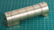
DSC_1660.jpg
The result does look reasonably "true" from usual viewing angles; so whilst not perfect I feel it is the best I will manage with my present skill set and so I must accept it for what it is. A tank engine would be easier.
 

Richard Gawler

Western Thunderer
A note on the shortened firebox.

DSC_1690.jpg
DSC_1691.jpg
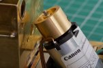
With the front of the firebox trimmed back, the gap in the boiler filled in and the adjacent boiler band taken around the boiler and not down the side of the firebox, the motor becomes visible but it does not foul the bulkhead which forms the front of the firebox.

DSC_1695 (1).jpg
The motor will end up almost completely hidden behind the centre splashers, a patch of dark grey paint should make it invisble.

I will guess the firebox was extended forwards to make room for a larger motor (this is a 1990s kit), but with something compact like a Canon CN22 there is space to spare and I think it was worthwhile to shorten the firebox.
 
Last edited:

Richard Gawler

Western Thunderer
Flywheel.

DSC_1712.jpg
I am amazed to discover, the firebox has room for a small flywheel. This is a 17 x 12 mm one from Markits, borrowed from Nellie my crane tank. There is 2 mm of space between flywheel and cab front, and another 2 mm between flywheel and top of firebox.

Whether a flywheel is terribly useful in a model driven by its own batteries is debatable, but I will let it stay and I have ordered up a new flywheel for Nellie.
 

Richard Gawler

Western Thunderer
Adding the boiler assembly to the model.

DSC_1732.jpg
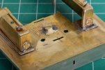
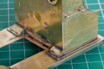
The model will be easier to persuade someone to paint (especially doing the lining) if the boiler assembly can be detached, so I am securing the assembly with some bolts and screws. I put a brass bar below the front of the smokebox, this is three layers of 0.5 mm brass with two holes tapped 10BA.

DSC_1738.jpg
Two matching holes in the footplate, and the head of the chassis fixing screw ground back to clear the brass bar.

DSC_1725.jpg
A short length of brass tube soldered into the back of the firebox to provide a dowel to locate the firebox onto the front of the cab, plus two nuts soldered on to accept mating bolts. I have also added a patch over an unwanted gap in the boiler so daylight won't appear here above the middle splashers.

DSC_1737.jpg
Three mating holes in the front of the cab. The one for the brass tube is located precisely, the other two are oversize. I have added the tops of the rear splashers and the beading around the bottom of the cab too.

DSC_1743.jpg
And so, under the footplate I have two 10BA screws holding the smokebox down . . .

DSC_1741.jpg
. . . and inside the cab I have two 6 BA bolts pulling the firebox back onto the cab.

DSC_1752.jpg
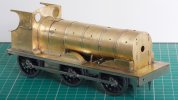
Resting the body onto its chassis I feel I have something which resembles a Y14.

I am relieved to say, the boiler assembly sits flat on the footplate before adding any of the fixings, so the footplate has stayed flat and hasn't developed a twist. The flywheel I mentioned this morning has had to come out, it is fouling against the brass tube. Nevertheless, I feel this is the essence of a model loco; the the structural work ends and the detailing begins.
 
Last edited:

Richard Gawler

Western Thunderer
Rear sandboxes and cab floor.

I want to do something constructive to make this model “mine”; all of the customising I have done so far has been structural (and unseen) and to omit features which the GER and later owners added after the locos went into service. I have made a start with the rear sand boxes.

DSC_1756.jpg
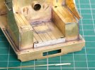
The handles are 0.7 mm brass wire, wrapped around a drill bit and soldered up and filed to shape. I tried to use some split pins but they are made of steel and rejected my attempts at soldering, wrong flux I guess. These are the first details I have copied from preserved loco no. 564 after my field trip to see her on 23rd August 2022 (photos in gallery).

The wooden boards on the floor of 564 run left to right not front to back but I have copied the steel plate in front of the firing hole from there too.
 
Last edited:

Richard Gawler

Western Thunderer
Six easy pieces - a pleasant day of adding and making detail parts.

DSC_1796.jpg
The bottoms of these handrails are butted onto the footplate, some small holes would be better. I wanted to drill the holes before adding the cab, but you need the cab to know the locations and then it's too late . . .
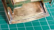
DSC_1762.jpg
These Y14s were built with a separate handrail across the front of the smokebox. Quite fortunate really; a lot easier than forming up the continuous handrail fitted later. I want the handrails to look like bare steel so I am using nickel silver wire instead of the brass wire supplied in the kit.
DSC_1792.jpg
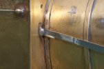
The reach rod for the reverser is half a millimetre too short. I tried bending the reverser arm to suit and it broke off, so I accepted the deficit.

DSC_1775.jpg
I put a length of brass wire to align the reach rod with the slot it can't reach in the cab, and filled the gap with solder. This bodgery will be hidden by a small cover later. The firebox is still free to lift away for painting.

DSC_1781.jpg
The operating rod for the front sanding gear doesn't reach its intended location in the firebox, but I will live with this so the firebox can come off for painting. I have added the bracket onto the splasher, this is not prototypical of course but it holds the loose end in the right place.

DSC_1810.jpg
This rod needs to sit on top of the footplate and not inside it, if you attach it onto the backs of the locating lugs instead of on top of them then the motion plate fouls the rod and stops the body fitting onto the chassis :rolleyes:

DSC_1771.jpg
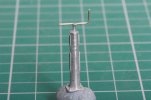
Returing to the tender for the first time in ages, the brake standard is nicely cast but I have cut off the cast handle and added one from wire, I think this looks better. The new handle is sitting in a hollow filed into the top of the casting, the 100 degree solder is a marvellous invention.

DSC_1778.jpg
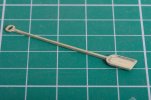
Looking for something easy to do I made up the shovel with a strip of scrap fret on the back of the handle so the model looks more substantial.

The empty frets are dropping like flies into my scrap bin. I am delaying the cab footsteps because they will stop me resting the superstructure on the bench, and delaying the lamp brackets because they are so fiddly, and really there aren't many more etched parts left to assemble.
 
Last edited:

Richard Gawler

Western Thunderer
Leaving room for the paint.

DSC_1800.jpg
I have returned to the screws holding the smokebox onto the footplate, elongated their holes in the footplate and added some washers. The result is, the entire boiler assembly has a little freedom in its final fore/aft location on the footplate, enough to make room for a coat of paint on both the back of the firebox and the front of the cab, or no paint on either.

DSC_1797.jpg
This is the no paint position. Some cheese head screws would be better. I have a choice between buying some 10 BA ones (easy) or buying an 8 BA tap to use the brass screws I already have (more useful in the future).

It's funny what the camera picks up but there is a witness mark of the motion on the axle here. This interference was resolved a while ago.
 

Richard Gawler

Western Thunderer
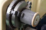
Hiding the worm gear.

DSC_1694.jpg
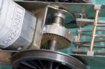
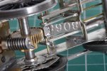
The teeth of the worm gear are always going to be shiny brass and they will rather spoil the look of the space under the boiler.

DSC_1818.jpg
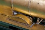
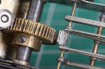
I have added a strip of nickel silver to hide the worst, and the sides of the gear can be blackened.

DSC_1813.jpg
This strip has got to be quite close to the gear to have much effect on the visuals. My method for holding this frustratingly small “filler part” was to leave the part over length but cut part way through (on the other side) with the razor saw . . .

DSC_1814.jpg
. . . and then break off the "handle" after soldering.

I don’t know what ‘8068’ was but a big thank you to @Martin Shaw for sending me his stock of empty frets, they are coming in useful for all kinds of extra parts on this model.

DSC_1820.jpg
Better. I can put some dark grey paint on the motor too.
 

Richard Gawler

Western Thunderer
Loco to tender coupling.

With the loco body in place it seemed sensible to sort out the coupling to the tender.

The kit provides the coupling bar. This seemed a bit wishy-washy if the loco is setting back on a heavy train so I added a second thickness. Then I made up two “shouldered bolts” from brass tube, washers and 8 BA screws.

DSC_1838.jpg

DSC_1842.jpg

DSC_1839.jpg
The minimum radius for this ensemble is now set by the coupling bar not the wheelbase of the loco. I could make a slightly longer bar one day for Setrack curves.

And now a word of caution!

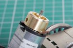
The loco has over-long crankpins carrying a second nut as a precaution against loss. Well, during the test running I picked up the loco and let a finger go under the footplate. The loco carried on running (because it is powered by batteries) and proceeded to nearly crush said finger between pin and footplate. There is a LOT of power in that Canon motor, and the pain continued until I managed to reach the controller with the remaining (untrapped) hand. This is the first time a model train has hurt me, as opposed to the usual culprits like sharp knives and the iron.
 
Last edited:

Richard Gawler

Western Thunderer
Crankpins, guard irons and sand pipes.

DSC_1883.jpg
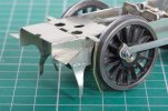
I have trimmed the crankpins to avoid further injuries, formed up the guard irons and added the sand pipes, and the wheels are now running with stainless steel shim washers instead of the offcuts of styrene.

The two triangular gusset plates here are going to sit below the spigots on the back of the buffer shanks and not in line with them, which is handy. If I abandon the idea of a flywheel and nothing breaks off I may have just finished the chassis.
 

Richard Gawler

Western Thunderer
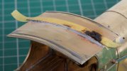
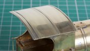
Cab roof.

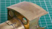
The cab roof supplied in the kit is for a cab after rebuilding to provide more headroom, so I have made a new roof.

I took the length by scaling from photographs and taking the model cab sides as a reference dimension. I think the finished size is about right, maybe half a millimetre too short – the discrepancy only showed up later when I started adding the details underneath.
DSC_1848.jpg
I annealed the brass to blue and the former was my offcut of 20 mm copper pipe plus my thumbs. Then I soldered the piece solidly onto the model.

When I laid a steel rule along the roof (from front to back), the rule never rocked; but moving the rule across the width of the roof from side to side I saw daylight varying from less than 0.2 mm to nothing. I will call this “good enough”, because I think it will look fine after painting. Though I am not sure how it ended up this way.

DSC_1850.jpg
The roof of the preserved loco (no. 564 at the North Norfolk Railway) has a supporting flange across the back between the cab sides. I cannot find this in period photos but it seems sensible to include it, there must have been something here. I didn’t fancy my chances of cutting such a piece from sheet brass so I used 1 mm square brass rod. Obviously this is well over scale thickness but the error only really shows if you pick up the model and look at from underneath.

The drawing shows L girders along each side of the cab (though I did not see these on the preserved loco) and I added the vertical parts of these from offcuts of the unused brake gear.
DSC_1911.jpg
The curved strip across the front is some 1.5 x 0.5 mm strip, I quite surprised myself how easy it was to set the curve across the larger dimension. One end clamped in the vice and the strip then manipulated around the side of an aerosol.

DSC_1924.jpg
The roof on the preserved loco has some metal strips underneath so I added these as well.

DSC_1900.jpg
The strips across the top are 1.0 x 0.2 mm brass and the masking tape was a guide for positioning. The tape kept the flux and the solder under control on one side when I was using the iron but didn’t fare too well with the micro flame.

DSC_1908.jpgThe result is a bit of a hybrid of what I can deduce from period photos, my photos of the preserved loco, and the drawings.

The brass strip is from Nairn Modelling Supplies via eBay, everything I have bought from them has been of good quality.

DSC_1917.jpg
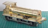
This seems like a good time to post a photo of how the loco looks at the moment. I cleaned the accessible bits with Solvol Autosol, the inaccessible bits with tomato ketchup, and tried to neutralise the residues of both with a solution of bicarbonate of soda in my ultrasonic cleaner.
 
Last edited:

Richard Gawler

Western Thunderer
Reverser reach rod.

. . .

View attachment 178526
I put a length of brass wire to align the reach rod with the slot it can't reach in the cab, and filled the gap with solder. This bodgery will be hidden by a small cover later.

I should be so lucky. The GER only fitted a cover over the reverser reach rod on locos fitted with a Westinghouse pump. The cover (supplied in the kit) is not an option for me.

DSC_1966.jpg
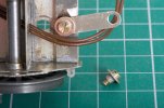
I have therefore had a go at making a representation of this end of the reach rod. This is a length of wire formed into a narrow oval, soldered onto an offcut of of fret and then filed flat. I added offcut of copper rod to represent the clevis pin, this broke off when I tried to file it to length but the solder left behind doesn't look so bad. I have put some black ink into the recesses to help them show up in the photo.

I have a hunch, the bifurcation of the reach rod ought to be symmetrical, but this is all a bit of a fiddle, near the limit of what I can manage with my fingers. So I think it will be wise to stop here.
 
Last edited:

Richard Gawler

Western Thunderer
Platform for experimental ballast weights.

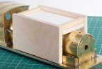
DSC_1971.jpg
This construction is a snug fit over the boiler and splashers. The idea is to provide a platform to hold ballast weights while I work out how much additional weight the loco needs to let it haul a four- or maybe five-coach train.

The superstructure with its castings will give me about 200 grams, much the same as the 8 oz weight I used earlier on the bare chassis. Maybe I won't need any more than this, but at least I am now ready for some trial running at the next club meeting.
 

Richard Gawler

Western Thunderer
Flywheel (second attempt).

DSC_1972.jpg
The Markits 17 x 12 mm flywheel which fouled my dowel from firebox back to cab front is now a 17 x 9.3 mm flywheel with a bevel on the offending corner, and the loco body fits onto the chassis with flywheel installed.

It is almost 43 years since I touched a metalworking lathe (for a school project) and the memories are flooding back. Of course, this also means most every precision item in the home able to fit into a inch and three-quarter swing is now at risk of being "improved" or of course "ruined", but at least I will be enjoying myself in the process.
 

Richard Gawler

Western Thunderer
Seatings on boiler fittings.

DSC_1988.jpg
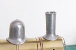
This is a very DIY approach to thinning the flares on the castings of the main boiler fittings. I have removed the flange from one end of the cotton reel and this end is inside the chuck. The chuck is also holding the strip of emery cloth into place. The speed is Slow.

DSC_1986.jpg
I have taken the bases of the dome and chimney as thin as I dare. The chimney is more fragile than it looks here.

The idea is to secure the castings with an epoxy resin, and then set the flares down onto the body of the model using something soft e.g. a bit of wood. I don't yet know whether this will work, but this is the idea.

I started to set up the flares by holding the emery cloth around the model and rubbing the fittings from side to side, but the lathe is much more fun.
 

Richard Gawler

Western Thunderer
A bit of emery wrapped around the boiler or smokebox and some gentle hand-lapping to fit…

Yes gentle is the word, and gentle lapping not tapping.

I am surprised how whitemetal can hold such a fine edge, this looks good but I could damage it very easily. The cotton reel is a bit narrower than the boiler and smokebox, so the lapping should be removing metal from the outer ends not the whole flare.

Edit:
I really should have covered the ways when using abrasives in the lathe. The problem is not the bits of whitemetal, it is the bits of abrasive that get dislodged during the process.
 
Last edited:

spikey faz

Western Thunderer
I think you were previously discussing the merits of having sub-assemblies bolted on or permanently fixed. Having just bent/broken the reversing lever on my Sentinel ash loco, I can definitely recommend the bolt-on approach as the pictures below show. Undo the nut and off with the part, to be repaired and bolted back in.
20230210_094705.jpg
20230210_094748.jpg
I have applied this method of assembly to all sorts of components and whilst it's a bit of extra work, it does seem to aid subsequent maintenance and repairs.

Mike
 

Richard Gawler

Western Thunderer
Mike I like this approach but I think it will be difficult for boiler fittings where at least in my hands a screw from underneath is likely to pull the fitting lop-sided.

What I am planning to do is to solder short stubs of brass tube into the tops of the smokebox, boiler and firebox. Place thin paper discs over these and secure the chimney, dome and safety valve castings onto the tubes but not the superstructure using Araldite.

If a fitting gets a knock then I will regard it as lost but I should be able to remove it without destroying the paint nearby, and then extract the brass tube using local heat from the iron and put in a new tube.

I am putting off attaching the boiler fittings for as long as I can, until I have run out of ideas for the soldering I need to do nearby.
 
Top