7mm At the Western End of F7

pete waterman

Western Thunderer
Progress from the electronic side of the work bench. These are the newly printed eccentric rods and straps for the Drummond T9; I think I got all the nuts and bolts in that Steph wanted to see. Now off to Laurie for the casting process and then to Nick for the build.View attachment 42937
Simon
Sorry to see your cab we have it as an etch if you wish to use it. The cab you have well Sorry Here a photo of the etched cab. Pete
 

Attachments

  • Halton-20150517-00641.jpg
    Halton-20150517-00641.jpg
    313 KB · Views: 109

SimonT

Western Thunderer
Pete,
thank you for your apology; the daft thing is that I didn't think to ask Laurie if he still had some etched ones! Even dafter is the fact that I thoroughly enjoyed scratch building the cab. Good to see you doing some modeling at Reading.

Simon
 

SimonT

Western Thunderer
Just finished in time for the weekend. I present rail based mobile accommodationIMG_1500.JPG

Good job that I took the photo as I spotted the missing brake wheels as soon as I put the photo in Irfanview. So not quite finished. Might go and look at Paul's site to check on white handrails, I should have looked while I was looking at the tents:rolleyes:.
Simon
 

SimonT

Western Thunderer
Richard,
the starting point is visible in post 157, a 30 thou plasticard box with 80 thou spine and ends. The bottom of the sides is kept under control by a length of heavy weight Evergreen strip. The 30thou was steamed into place over the kettle. I then used 10thou thick strip to make the seam line. The cleats were from 20 by 60 thou strip. Various other thicknesses gave the lines of the folds. It was then Squadron Green putty time to blend everything in followed by sanding smooth, guide coat of primer and around the fill, sand, prime circle until done. It still needs a bit more but I decided that I had run out of time and painted and weathered. I can always go back when time allows.

Simon
 

SimonT

Western Thunderer
Time for the evidence of some loco modelling on the work bench.
Firstly the pannier tank was halted while I worked out how complete the cab and bunker. Well eventually a workable solution came to me and here is the present state of play.
IMG_1524.JPG

As you can see, all the cab and bunker plate work is complete. The backhead and fittings are all in there but can be removed for painting and finishing. The backhead is really in there, honest...

IMG_1525.JPG
Please excuse the best the IPhone can do. The answer to how is .....
IMG_1529.JPG
The cab floor has been removed between the hanging plates and a replacement floor, onto which the backhead is fitted, can slide and swivel into position. The cab front has the gauges and lubricators attached. As you can see, Pete's boys make the fold up footplate part of a fold up jig and I am one of the klutz that cannot make a neat job of it - sorry Pete and Laurie!

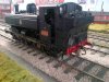
Also on the bench is this bit of heavy metal.
IMG_1521.JPG
This should be quite interesting to get it to go around 6ft3in radius! And no, you cannot see under the footplate!

Simon
 

richard carr

Western Thunderer
Simon

I take it that is a 2-8-2 ?

I think you will find it relatively easy to make it go round that radius a curve, the key is getting enough swing on the pony trucks.

My 9f goes round curves that tight so long as you give it enough room between tender and loco.

Richard
 

SimonT

Western Thunderer
Richard
The 42/52/72XX are all very tight on the pony truck clearance on the cylinder, as in there is no clearance. But I do have a pragmatic fix that works on 4294 on the layout. The rear axle is also a little tight on completed 56XX. So there is a plan for this large bit of fun and games.
Simon
 

Cliff Williams

Western Thunderer
The trick I used on my 42xx was to move the pony pivot forward by a small amount, it is a trade off we have to make sometimes!
 

pete waterman

Western Thunderer
Hi Cliff as you know my 42xx go though 6ft 3in and I so far have had no problem with my 72xx. If you want to make sure take a little of the back of the cylinders that will give you all the movement you want.
 

SimonT

Western Thunderer
My solution was to move the pivot hole on the bogie frame backwards to give a longer swing; similar result as Cliff obtained by moving the pivot point. I have of course made things more difficult by doing the S7 thing. Gauge widening of .5mm helps as well.
 

richard carr

Western Thunderer
Simon who's wheels are you using, the scale thickness is probably only 3.15mm but that is hard to achieve with a slaters wheel as your starting point.

Richard
 

SimonT

Western Thunderer
Richard,
the Slaters wheel has been re profiled and the contact point is the flange against cylinder front and the wotsit valves. It is not a wheel thickness problem.
Simon
 

SimonT

Western Thunderer
Meanwhile, back at the digital end of the workbench (as opposed to the fingers and fumbs end), here are the printed masters for GWR pannier tank hornblocks and axleboxes. These will be going off to LG for casting and adding to his range. A spring will go between the two spigots to provide suspension. The printed prototype works nicely but it is currently in a safe place, so I cannot provide a photo of it. Should I remember where the safe place is .....
IMG_1538.JPG
Simon
 

SimonT

Western Thunderer
Pete,
Simon thought you had seen these
I have but wanted to do something slightly different! I have never been fond of the long 12BA screw through the spring from the top or the bottom - you don't see them on other sprung systems such as car suspensions. (Now someone will post a picture of such a set up on a vintage motor - bound to be French). I developed the idea over a day with four gradually improving prototypes as the idea developed. The spring is held in place by the pins on both the horn and on the top of the axlebox. These pins act a bump stop at maximum compression of the spring. The axlebox rides at mid compression of the spring, all achieved by weight distribution.

I'll let you know if it works.
Simon
 

SimonT

Western Thunderer
One of the high lights of yesterday was seeing Laurie Griffin and being handed a plastic bag of brass bits. Accordingly, showing disappointingly poor self control, I have been doing a bit of fettling.
IMG_1627.JPG
Hopefully I can get them onto the frames tomorrow and that then means that I need to get onto the lathe to sort the wheels. I'm now rather keen to get this little loco finished and in to traffic. As to the castings, Laurie will have the bits in stock for all the Pannier tank builders out there.

Work was interrupted for 15 minutes before 1500 to watch a large tin triangle and 9 red Hawks make a lovely shape (and even better sound) while they held before their flypast at RIAT. Check out the film of yesterdays Vulcan display on Youtube - awesome!

SimonT
 

adrian

Flying Squad
One of the high lights of yesterday was seeing Laurie Griffin and being handed a plastic bag of brass bits.
It's great to see the process from 3D print to casting - lots of potential ideas! Are you just soldering the keeper plate on or is there enough meat to drill and tap a thread?
 
Top