You are using an out of date browser. It may not display this or other websites correctly.
You should upgrade or use an alternative browser.
You should upgrade or use an alternative browser.
Crane Locomotives
- Thread starter spikey faz
- Start date
Richard Gawler
Western Thunderer
Please Mike, are the new buffer beams from solid brass? I might re-do the wooden ones on my 'Nellie' crane tank one day.
spikey faz
Western Thunderer
They are indeed. Brass strip from Holiday Holidays.Please Mike, are the new buffer beams from solid brass? I might re-do the wooden ones on my 'Nellie' crane tank one day.
Mike
spikey faz
Western Thunderer
The drawing I'm using hints at there being buffer beam safety chains, and there's a picture in the book "The B4 Dock Tanks" by Peter Cooper that has them. So I've fitted some from CPL.
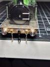
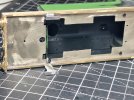
I also managed to re-use the Dapol footplate steps. Small strips of brass soldered to the footplate to support the steps. I was going to glue the steps in place, but by some miracle was able to solder them on instead! Superglue as a backup.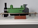 Mike
Mike


I also managed to re-use the Dapol footplate steps. Small strips of brass soldered to the footplate to support the steps. I was going to glue the steps in place, but by some miracle was able to solder them on instead! Superglue as a backup.
 Mike
Mikespikey faz
Western Thunderer
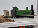
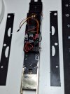
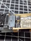
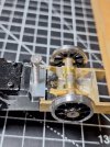
I've now made a start on the rear frame extensions. There were already some conveniently placed holes for the plastic guard irons (now removed and will be repositioned at the ends of the extended chassis) which I've drilled right through. Couple of nuts and bolts to hold the frame extensions on.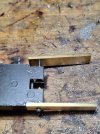
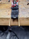
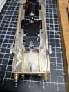
I'll be adding full length Plastikard overlays to the frames.
Mike


I'll be adding full length Plastikard overlays to the frames.
Mike
spikey faz
Western Thunderer
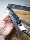
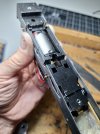
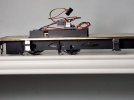
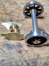
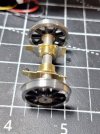
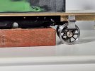
Thoughts are now turning as to how I might attach the new trailing axle. I was thinking of Slaters hornblocks albeit with very light springs, just to hold the wheels lightly in place on the track. But I'm not sure if there's room. There is also a conveniently placed hole in the underside of the chassis that could possibly be used to mount a pivot for a simple trailing truck.
Mike

Mike
spikey faz
Western Thunderer
spikey faz
Western Thunderer
Richard Gawler
Western Thunderer
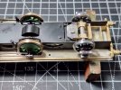
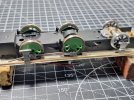
Please Mike, what is the lump in the chassis near the buffer beam? I am guessing a part of the Dapol chassis block which you are retaining to look like a counterweight for the crane?
spikey faz
Western Thunderer
Hi RichardPlease Mike, what is the lump in the chassis near the buffer beam? I am guessing a part of the Dapol chassis block which you are retaining to look like a counterweight for the crane?
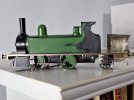
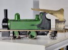
Yes, it's part of the Dapol chassis. It looks a bit odd, probably 'cos the cylinder block is not fitted. Once that's back in place all should make a bit more sense.

I'm trying to keep the progress on this project moving at pace as my enthusiam is starting to flag a bit. Despite just renewing my Scale7 membership for another year (the cheque's in the post!) I keep casting my eyes over my G Scale engines!

Mike
spikey faz
Western Thunderer
spikey faz
Western Thunderer
spikey faz
Western Thunderer
spikey faz
Western Thunderer
spikey faz
Western Thunderer
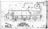
I've not much info to go on, other than the above plan. Any advice/ suggestions are very welcome.Curious looking beast.
Interesting (and logical) that the slew bearings are so widely spaced.
I wonder how the bunker was designed to take the side-loads down into the frames.

Cheers
Mike
Giles
Western Thunderer
I would have thought that the bearings were mounted in a 'box' of which we are seeing the side frame? That would perhaps sit tight between the frames, which must be beefed up somewhat not to be twisted as the crane slewed with a load. There must be inner frames behind the trailing wheels anyway, but even so......Curious looking beast.
Interesting (and logical) that the slew bearings are so widely spaced.
I wonder how the bunker was designed to take the side-loads down into the frames.
All conjecture, but that's how I would have approached it.
Giles

