Genghis's 7mm Workbench

Genghis

Western Thunderer
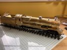
I continue to make progress with the I3. I had a bit of a setback (entirely self inflicted) when I realised that I had secured the boiler assembly not quite horizontal. I only noticed this once I had completed all of the soldering around the saddle. It was 1mm over the length of the boiler so I certainly couldn't live with that. SO out came the gas torch after which I had to rebuild the saddle assembly. Since then things have gone well.

IMG_2798.jpg

The roof is detachable.

IMG_2799.jpg

IMG_2800.jpg

IMG_2801.jpg

Most of the etch work is now done. I'll wait to fit the coal rails, steps and lamp irons until I have marked out the boiler for the handrail knobs and washouts.

This is a surprisingly large loco.

Edit: now seeing the photos I need to check if the cab is on square......bother!
 

Genghis

Western Thunderer
Coming along nicely Genghis, what livery are you going to paint it and how heavy will the finished loco be please?
Regards,
Ian
LB&SCR Brown.

Not sure about final weight. I have some lead that might be added, but this will be DCC fitted with sound and stay alive, so I don’t know how much room there will be. It’s already quite heavy.
David
 

Genghis

Western Thunderer
Have got about as far as I can now before I get home.

The instructions warn that frame spacer D may interfere with the cab floor: it does a little so some bodging was in order to get clearance:

IMG_2816.jpg

IMG_2817.jpg

I still need to fit pick-ups, some washouts, a regulator handle, and the water balance pipes but apart from these I think we are there now.

IMG_2818.jpg

IMG_2819.jpg

IMG_2820.jpg

IMG_2821.jpg

IMG_2822.jpg

IMG_2823.jpg

IMG_2824.jpg

A nice kit, which is a pity: with a few tweaks it could be an excellent one......

David
 

Genghis

Western Thunderer
The I3, B16/1 and a pug are now at Paul Moore's magical workshop for transformation so it is time to get on with the next commission: a Gladiator/Fourtrack J25. This is going to be an out of the box build. I am not expecting any problems as this is 90% the same kit as the J21 that I did previously. I thought that I had rewritten the instructions for the J21 using photos etc from the build. If I did I cannot find what I did with the copy. Pity that. I will do the same for this (and hopefully not lose them) but I don't intend to bore you with everything.

Starting with the tender frames. There is a choice of a fold up or construction. I have chosen construction. The only variation from the instructions provided is that I elongated slightly the central holes in the frames so that the axle bushes have a little vertical movement. The frames are quite long and getting 6 wheels on the ground at all times on anything other than perfectly aligned track would be impossible. This give some leeway. The centre bearings had a .7mm hole drilled in and a length of wire soldered in to stop teh bearing rotating and keep it aligned axially.

IMG_2866.jpg

IMG_2864.jpg

I may make a start on the loco frames next.
 

Genghis

Western Thunderer
So onwards and upwards.

The loco frames were almost straightforward. I decided that I would include some give in the centre axle in the same way that I did for the tender frames. It is quite a long wheelbase for a small loco. That worked out quite well, but raised the question of how to joint the coupling rods. On the J21 the frames I built had a rigid base with solid coupling rods, but it developed a problem and didn't run particularly well, so Paul Moore made another one for me. I forgot to ask him if the rods are solid or not. Anyway, on the J25 the coupling rods on the centre axle are each a half thickness etch with a dummy joint forward. If I put a pin in the dummy joint the rods will try to pivot at the joint and the crankpin. I don't think that will work, so for now the rods are not secured together and it is running as a pair of 0-4-0's sharing a common axle. It seems to work but I have something in my failing memory banks that says it is not a good idea to do this. Any advice?

That isn't quite the whole story for the rods. The kit is now rather old and while some modifications have been done over the years, I think the frame etch is an original hand drawn job. I would normally build the rods first and use them to check the axle spacing but for some strange reason I didn't do that this time. It is always a crossed finger moment when you see if it rolls with the rods on first time. Well it didn't. It would run freely as an 0-4-0 with rear and centre wheels connected, and even when the front left hand side rod was added, but the addition of the front right hand rod caused a lock up at forward and rear centres. The rod is perhaps about half a mil too short but by slowly elongating the leading hole I got it to run freely.

One other problem was found. I fitted the cross wires for the top of the brake hangars but they then were at a strange angle to the wheel. I redrilled the holes about 2mm closer to the wheels and that did the trick. I wonder if this is a hangover from the common ancestry with the J21. Although the frames for each are different the kits share the same body etches with additional parts for the J21, (but using the same brakes for both and the hangars are too small for the larger wheeled J21). So I have it in mind to have the two kits redrawn. They will still be able to share many parts but really need their own etches.

I did my usual trick of making a torque reacting bracket from scrap etch. This secures the ABC mini and Maxon motor in place. I will clean up teh wheels just before I return to UK or they will rust like crazy here. The axles are well oiled to keep them safe.

IMG_2883.jpg

IMG_2884.jpg

Next job is to toss a coin and see if it is loco or tender body next.
 

simond

Western Thunderer
David

it is running as a pair of 0-4-0's sharing a common axle. It seems to work but I have something in my failing memory banks that says it is not a good idea to do this.

I can't see any reason why you shouldn't pivot the two halves of the rods on a common crankpin. The edges of the etched rods might be a little thin, so it might wear loose fairly quickly, but otherwise, I would bet there are many locos running around like that.

The other option, of drilling the "proper" hinge and pinning there will be fine, provided that after you have drilled it, you cut off (or much enlarge) the hole in the front rod that engages with the centre crankpin - otherwise it'll be more rigid than you require.

cheers
Simon
 

LarryG

Western Thunderer
I use the epithet regularly... :cool:

That little 2-6-2T looks nice. I have always felt Ivatt on the LMS is very under rated by history while people like Robinson, Maunsell and in particular Bulleid, are praised for producing piles of junk for their employers. Ivatt's little masterpieces worked far beyond the LMS and they and their Riddles counterpart were the saviour of the Eastern and Southern regions of BR.
 
Last edited:

Stephen Freeman

Western Thunderer
Looks an excellent job but if it is an early kit, you might want to look at moving the cylinders in a bit as they are known to stick out, I am sure this has been commented on before, the BR standard had the same issue. I think recent kits may have been corrected.
 

LarryG

Western Thunderer
Didn't like to comment, but it does look like one of the sticki-out cylinder jobs, as borgrail mentioned. A few came in for painting years ago and I wondered at the time why some builders had not modified them. Is it a particularly big job?
 

Genghis

Western Thunderer
It's definitely a sticky out job. Would need to cut back the cylinder castings and reduce the width of the motion bracket etch, which is outside of the tank sides. I did comment to the owner that the cylinders are a long way out. Gives plenty of clearance between cross head and coupling rod but means that the connecting rod is at a strange angle to the slidebars if the big end is close to the coupling rod. I packed it out with washers.

My only input to this build really has been to get the valve gear fitted and working and add details, mostly on the bunker rear. If I was starting from scratch I would probably have made the mods (or asked DJH if they can supply correct bits) but if the owner is happy with it then I am going to leave it.

David
 

Genghis

Western Thunderer
Well it is time to leave the 25 degree warmth of Taiwan and head for cooler climbs tonight. As well as the J25 and Ivatt, this will be in my luggage:

IMG_2952.jpg

Had a mail from Warren recently asking where were the brake beams? Also missing from this kit, so there must be a supplementary etch panel somewhere for this. I've probably packed it in other locos not realising it was an orphan........ bah! Still I do have some others I think. A note to be added to the packing list I think (also to say don't forget the safety valves.....)

The piston rods on these locos are as long as the Amazon and have to be guided through a long boss on the slidebars and then the gland on the cylinder covers. I was worried about alignment but it worked out OK. The mould for the slidebar casting is past its best and is missing the core that puts a pilot hole through the long boss. I've had a replacement mould on order since March and am hoping that comes through soon as we have more of these kits to pack.

David
 

Dave Holt

Western Thunderer
On the Ivatt tank, the rod/tube linking the lubricators, below the smokebox, should not be there.
The push-pull fitted locos did have a balance pipe linking the bottom of the outside steam popes, but this was not present on the non-fitted locos.
Dave.
 

Genghis

Western Thunderer
On the Ivatt tank, the rod/tube linking the lubricators, below the smokebox, should not be there.
The push-pull fitted locos did have a balance pipe linking the bottom of the outside steam popes, but this was not present on the non-fitted locos.
Dave.
Thanks for the info: it was there when I got the loco, so I'll see if the owner wants it out!

Seriously, I am always impressed by your technical knowledge, so please keep going with the comments.

David
 
Top