Monks Ferry: a layout for the Grandchildren.

jonte

Western Thunderer
Parts to construct the light signals having been arriving piecemeal fashion:

IMG_2873.jpeg

Ladders from Wizard Models.

I await some nickel silver sheet for the bases and landings, but most importantly of all, the shrink wraps which I ordered before anything else and which I’m informed are currently ‘behind schedule’. Until these arrive and are fitted to the wires from the rear of the signals, I cannot determine which u size U channel to purchase and thus the distance to space the I beams on the landings to which they will be glued. Was hoping to have made a start on them before a break at the weekend (fir several days), but guess I’ll just have to put the exercise on the back burner.

In the meantime, and with the odd spare moment, I’ve been painting again.

Mainline track and points have a dark rail which will have to do to save time as they’ve all hit to be cleaned up (again) and tested:


IMG_2871.jpeg

The mainline point to the left in the below has the diverging rail left a lighter chocolate colour as it’s the entry to the MPD:

IMG_2870.jpeg

The plain track and points within station and yard areas are painted in lighter chocolate, which will receive several quick washes if a couple of mixes in an attempt to match that in the earlier photo of W’loo:

IMG_2872.jpeg

Just to evidence that I haven’t quite up the ghost……yet!

Cheers.

jonte
 

Yorkshire Dave

Western Thunderer
My dad told me to always twist the cable ends, before soldering, he did tell me why, but I can't remember why.

To stop the strands spreading/separating when heat is applied and ensure there are no stray strands which could create a short. I've noticed today, soldered cable ends are rare and now usually have a small barrel crimped onto the terminating end.
 

jonte

Western Thunderer
My dad told me to always twist the cable ends, before soldering, he did tell me why, but I can't remember why. Dad inspected and tested electrical equipment before dispatch to the MOD.

Thanks, Phil.

Yep, all soldered ends twisted and tinned on rails and on the signals. :thumbs:

The ones on the solenoids were intentionally splayed before tinning to create a greater surface area to achieve a solid joint and make ‘adhesion’ easier (plenty of room between adjacent wires).

The excess wire from the unsoldered ends will be cut to length once everything is in place.

Jon
 

simond

Western Thunderer
To stop the strands spreading/separating when heat is applied and ensure there are no stray strands which could create a short. I've noticed today, soldered cable ends are rare and now usually have a small barrel crimped onto the terminating end.
Soldered wire is more prone to fatigue failure in a high-vibration (eg vehicle) environments. Properly-applied crimps are more reliable long term.
 

jonte

Western Thunderer
Thanks, chaps.

Looking at the above photos, the bunching together of the points whilst they dry is creating a sort of optical illusion which makes it appear as Phil @Phil O alluded to.

My apologies. Should have waited till they’d dried and spread them about a bit; just wanted to catch them whilst in natural light.

jonte
 

jonte

Western Thunderer
Following a week or so away and a busy period prior to and after, I snook away from the family presence for a brief hour or so earlier today to try a light wash or two on some track parts that have been lying idle for the duration.

From the earlier photos, it can be seen that the rails are a dark chocolate type colour peppered with areas of an ochre-ish hue, so a thinned Humbrol 62 was wafted over the chocolate base, itself washed over a lighter brown (it’s just the tracks in the station and sidings areas that will receive this treatment).

The results were mixed; mixed not being the best description of the result of the days’ briefest of play. The sunlight shows it as basically a bright wash:

IMG_2879.jpeg

In truth, the photo belies the outcome: it’s still chocolate tinged with ochre but not enough. The settlement of the wash in the high areas gives it the impression that it’s much lighter.
A further light wash made not much difference, but the last photos taken of the results inside under ‘white’ light which was slightly diffused, give a better impression:

IMG_0142.jpegIMG_0143.jpegIMG_0144.jpeg

A further wash when time permits will create a better impression of the prototype colour me thinks, which can then be knocked back with washes of the black/brown shade used earlier on the sleepers. That’ll do for me this time.

The last job in this long list of jobs to modify these toy points will be to open up the pin holes with a drill bit such that the track pins can be countersunk and filled over to hide them.

Just before I left, the last piece of the shopping list fir making my own colour signals arrived, ie the heat sink pieces seen here with the other items fir construction:

IMG_0145.jpeg

Whilst away from home, I gave some more thought to the pending signal construction and decided that it might be best to make my own canopies from brass or nickel silver and just use the plastic ones in the set as templates.
In this way, I can drill the holes to take the fat end of the leds such that the whole length of the led lamp can be situated to the front, which means tgat only the leads will be present to the rear, thus reducing the boxy look at the back further.
I’ve got some brass tubing which can be soldered on to form the lens covers which can be filed to the right profile.

Well that’s the idea.

Thanks for looking.

jonte
 

jonte

Western Thunderer
With an odd hour or so spare since my recent last, I subjected the points to a couple more washes. This time, upside down to give a more even hue over the height of the rail. A repeat of the leather was applied only this time stippled in an attempt to replicate the piebald appearance of the weathering to the rails, especially in Waterloo. This was repeated, only on this occasion, I reached for a cream colour added 2:1 to the leather (Humbrol 121, i recall, but any yellowish colour will do). This was because I’ve saved another photo from an online vid which shows a paler shade of ochre. Anyway, where it is currently:

IMG_0166.jpegIMG_0165.jpeg

As mentioned previously, this will all be toned with washes of a black brown colour similar to that of the sleeper wash.

Unusually, I had a free modelling day today, although I was reluctant to start. Why? Well, I thought it about time to make a start on the signals now that the materials were to hand. However, whilst I had given much thought to the direction construction would take in the absence of doing any modelling whilst away from home, now that I’m back, I’m just not in the mood.

So, I just gave the track (above) another wash.

But during lunch, aware that time at the bench is restricted more than ever at present and perhaps so for some time to come, if I’m to complete anywhere near my set time, I dragged myself out to the workshop and picked up the nickel silver sheet which I thought was a good place to start.

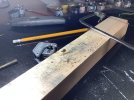
To assist with cutting and marking out, I stuck a length of masking tape to one end and drew a line approximately the width of a BR(S) canopy (slightly larger dimensions than the plastic one I was intending to use and which was under scale at HO) and then made several passes with a Stanley knife:

IMG_0155.jpeg

Then I bent it steadily downwards along the line using the table edge until it broke off:

IMG_0156.jpeg

Then I cut tthe strip into sections, one for each canopy of six using a small square to keep things as straight as possible :

IMG_0157.jpeg

They were elongated at the base unlike the American based plastic ones I’d intended to use, and more in fitting with the SR type, but essentially to satisfy an idea for locating the e canopy and lights in the main stanchion for easy removal (I found out later this was a bum steer). Also shown is some brass tubing I had which I intend to use for the lens covers, and which fits the thin part of the led like a glove:

IMG_0158.jpeg
They were elongated sections cleaned up and placed one on top of the other for shaping and drilling, held together by a washing peg clamp to solder each side together:

IMG_0159.jpegIMG_0159.jpeg

The joined sections in a modelling vice for shaping with a variety of files and drilling:

IMG_0160.jpeg

Whilst searching for my bigger files, I discovered another piece of brass tubing which handily is wide enough in diameter to allow the wider section at the base of the led to fit through, which means I can locate the whole length of led inside the lens covers. The section of tube intended for the lens cover and which is also a snug fit for the body of the led is shown (telescpoically) inside it:

IMG_0161.jpeg

Also shown, are the two sections of square tubing, the wider one of which will form the main stanchion. My idea hatched whilst away, was to solder the canopy to this inner section to allow its easy removal from the stanchions should a bulb fail. However, try as I might, I couldn’t get the two wires inside, so that was that idea out of the window. I’ll just have to run with the single wider stanchion which easily accommodates the wires:

IMG_0162.jpeg

I’ve decided that the cathodes for each led can be solder to the rear of the canopy fir each signal, a wire then soldered to the base of the stanchion to which a resistor can be attached (as long as the lights don’t illuminate at the same time a single resistor can be used).

The light canopies after using a wider drill fir the leds (they will be opened up with a reamer when the time comes):

IMG_0163.jpeg

………and finally separated and cleaned up:


IMG_0164.jpeg

Ah well, not a bad start considering My lacklustre mood.

I was going to add something else, but I’m afraid it’s gone……..

Until next time.

jonte
 

jonte

Western Thunderer
Paid a visit to the workshop late morning to check on the progress of the track sections, which had received a light wash of the black/brown sleeper wash, used on the sleepers, yesterday morning.

Satisfied I’m going in the right direction - the Waterloo vibe at last looming into view - I’ve decided that the final effects will be applied by airbrush afterall, but that will be for another day. I’ll carry on with the plain track in these areas in the same fashion when time allows:

IMG_2889.jpeg

So reluctantly, I turned my attention once more to the embryonic light signals.

For something so apparently simple, there is (and has been) and continues to be much to consider, especially in relation to which aspect of the build to attack next. Also, it’s only when you have the bits to hand that it’s sometimes apparent that what might work in theory is just not gonna work in practice/practise.

Anyway, to cut to the chase I decided the lens covers would be a good place to start (another example of an area where I’ve changed my mind about stuff…….it was to do with the lamp wires being too near to the rear of the lens canopy in an attempt to reduce the boxiness to the rear, which creates an unnecessary risk with regards to shorting as the signal will be ‘live’).

I’d considered cutting thin lengths of brass sheet for the covers which could be annealed and bent to shape. In this way, it would be easier to cut the rounded profiles at the ends. But life is too short, especially as there are more just one or two required, so I returned to my idea of using brass tubing. However, as I had intended to use my modelling tube cutter to ensure truly vertical ends, would short 6mm lengths be difficult to file to profile (in half), and would each be the same diameter? In the end, to address this issue, I decided to file the length of tubing fir all twelve required :

IMG_2892.jpeg

So, with the use of my handy tube cutter out of the question, I resorted to using a piercing saw to cut off a single section which took ages as the teeth on the blade kept catching on this miniscule piece of metal.

The result placed for scrutiny:

IMG_2894.jpeg

…….and this to show it standing on my sawed end:

IMG_2895.jpeg

Hmmmmmm…..not sure I can maintain this accuracy.

Do I now attempt to profile the ends? I’ll consider this while cutting the rest.

Cheers for now.

jonte
 

Attachments

  • IMG_2893.jpeg
    IMG_2893.jpeg
    388.5 KB · Views: 1

jonte

Western Thunderer
With all twelve lens covers fashioned (in a fashion), I set about making a jig to assist with soldering them to the canopy.

So after opening up the holes in the canopy with a reamer such that the bulbs were a comfortable fit, I started to build a simple jig:

IMG_2897.jpegIMG_2898.jpeg

………and then soldered on the first lens cover:

IMG_2899.jpeg

……. followed by the second:

IMG_2900.jpeg


Releasing them from the jig, I saw that despite everything being as true as possible they were sitting skew-whiff:

IMG_2901.jpeg

This was probably due to the lining up by eye (unreliable) of the brass tube in the vice when filing it, in what was supposed to be half. Additionally, in an attempt to make the solder joint neater after releasing the parts from the jig, I knocked the lower lens cover out of true:

IMG_2902.jpeg

One of the lens covers is slightly longer too…….an adjustment can be made later I suppose.

So back into the jig it went to return it to true and then files were used to straighten up the skewed lenses:

IMG_2903.jpegIMG_2904.jpeg

In all honesty, I’m not that fussed but hoping that the addition of a landing, handrails and landing will improve matters.

But at least I enjoyed the experience this time.

So on we go.

Cheers.

jonte
 

jonte

Western Thunderer
A further post briefly to say that I’ve ditched the product of yesterday’s work.

I really wasn’t satisfied with the result, but it came as no surprise. I’d cut corners to hasten the outcome and changed tack partway through resulting for instance on light jokes being off centre and tubes being unfit for purpose. I should have dug out the pillar drill, marked out with more care and used annealed brass for the lens covers which would have been thinner and more realistic. Plus I could have profiled them in the flat. Water under the bridge.

Thus I’ve returned to the plastic HO ones. I’ll have to accept thicker appearance at the back, but at least it’ll speed up the process. One plus point was that opening up the lens holes with a reamer meant they sat further in thus less protrusion, so a plus point I suppose.

Still, it’s not a quick process as it took a whole morning and earlier in the afternoon just to produce a single landing. I also had to dig out an 80W iron to solder lengths of brass together. The 25W wasn’t up to the job.

Anyway time has run out for now so I’ll leave you with a couple of photos of todays work:

IMG_2905.jpegIMG_2906.jpegIMG_2907.jpegIMG_2908.jpeg

There’s an overhang on the platform at the back for handrails.

The I beam doesn’t show too well here.

Cheers for now.

jonte
 

jonte

Western Thunderer
It’s dull and wet in the centre of the Universe as I write, which reflects my low mood rather well. My only hope isthat a certain fool of a company man, who has graced us in these parts with his presence of late, slips and irrevocably injures himself. If only……….I digress.

With my time at the bench limited of late, and about which I keep harping-on, I decided to just slip out for ‘half an hour’ on Sunday evening to make the most of time and get an upright of those pesky colour light signals (semaphores are a complete doddle compared to these!) well, upright, once and fir all!
What a pain the a***!.
Despite my best efforts with the jig, everything just kept slipping and the darned iron bits were simply way too big for the relatively tiny parts which required piecing together. Singed pinkies were the least of my worries. Ideas aplenty to resolve, and a disarray of tools didn’t help and in the end, I just had to walk away disheartened and in foul mood seeking a telephone number for Eckon models. When I returned to the living room, my wife - whom I’d promised to be out no more than half an hour - was in frosty mood. Railway modelling…………….

Grand parenting duties over the last couple of days gave beneficial (to the benefit of mental health) time away from the bench and which also afforded moments of reflection.

Thus I made an early start thus morning (before one of my grandson’s arrives) to try out (yet another) idea. Hopefully this will work……..

The untidy workshop that greeted me this morning:

IMG_2909.jpeg

Another failed attempt from Sunday evening:

IMG_2910.jpeg

A new jig:

IMG_2911.jpeg

A new extreme in an effort to ensure ‘straightness’:

IMG_2912.jpeg

(You can see the stanchion out of true).

Yep, I,ve resorted to drilling holes in the brass tubing for bith jig and stanchion of signal (the signal will have a section of nickel silver soldered on over the top to hide the hole, something I’ve seen on some LNER variants).

I’m also intending to strip down the one seen in the pictures above which I can use for a test, and then commence a new method of construction, one which will allow better access to the parts with a bigger iron (I never realised so much heat would be required first such small parts). I’ll also be trying out solder if varying temperatures.

Here’s to trusting to luck, with Eckon’s head office number locked into the memory of my phone; just in case.

jonte
 

jonte

Western Thunderer
Started well:

IMG_0169.jpeg

The second piece also attached holding iron to outside of piece fir easier access and 145 solder fir less heat,which worked:

IMG_0172.jpeg


Problem was that the residual solder from the initial test (which I filed flat as best I could) rendered the piece out of true in the jig, only apparent on release.

Outcome: I’m going to plan B which uses the option of a gantry over the station throat. I’ve a Ratio gantry in stock, but reckon that the Dapol version would suit the theme better, perhaps with some H beam replacement supports I’ve got although I might just build as is, as time is of the essence.

Thoughts have also returned to the issue of third rail for my electric set. Not sure about clearances using train set track so will probably just lay some lengths along the platforms as a nod to the real thing.

jonte
 

Roger Pound

Western Thunderer
Jon,

Your patient persistence is somewhat wondrous to behold - to me at least. As you are aware I would have got some Ekon signals in, or even Hornby Dublo signals, and taken the relatively easy way out, but that's me. My limitations in metalwork would not even permit me to think of embarking on the path you are following. With all your pressures on your time, I wish you success and this will perhaps allow the running of trains to happen ere long, otherwise it may come to the stage of your grandchildren becoming active builders on the layout scene to give Grandpa a hand...........;)!

Roger (with tin hat firmly fixed. :))
 

Alan

Western Thunderer
I'm glad I know the limit of my skills and I remember that even in 0gauge I'll be looking at the layout from a scale distance of some 40 yards and in 00 it would be something like 100yds. Personally I stick to the KISS principal.
 

jonte

Western Thunderer
Jon,

Your patient persistence is somewhat wondrous to behold - to me at least. As you are aware I would have got some Ekon signals in, or even Hornby Dublo signals, and taken the relatively easy way out, but that's me. My limitations in metalwork would not even permit me to think of embarking on the path you are following. With all your pressures on your time, I wish you success and this will perhaps allow the running of trains to happen ere long, otherwise it may come to the stage of your grandchildren becoming active builders on the layout scene to give Grandpa a hand...........;)!

Roger (with tin hat firmly fixed. :))

Welcome words of wisdom indeed from one so worldly wise as yourself, ol’ friend, and I can’t contend with any of it :thumbs:

In fact as you sensibly suggest, I originally considered using the Dublo variants as platform starters and purchased two sets of these for the purpose:

IMG_2919.jpeg

I suppose nostalgia too played a part.

Here’s one of the sets being tested just after purchase:

IMG_0145.jpeg

In a weakened moment after my recent failures, thoughts turned once again to the possibility of using them, and I re-read an article on converting them to led use (my 3mm variants are just right and don’t poke out as far as the original filament bulbs which tended to overheat).

I may still use them, but primarily I’m looking to develop a gantry set, which I recall were in use at the likes of Queens Street in Glasgow. Eckon are rather smart, but somehow I can’t help feeling they look a little too modern fir the washed up City terminus I’m seeking.

As always, Roger, your kindest thoughts and suggestions are always appreciated.

Best wishes,

Jon
 

jonte

Western Thunderer
I'm glad I know the limit of my skills and I remember that even in 0gauge I'll be looking at the layout from a scale distance of some 40 yards and in 00 it would be something like 100yds. Personally I stick to the KISS principal.

Unfortunately I never learn, Alan.

I enjoy making things and the parts required were purchased with the right amount of enthusiasm required. In the interim, it waned; experience has shown that it will return, but as Roger @Roger Pound correctly pointed out, time with this project isn’t on my side, so a quicker fix is required. I’m sure that in time, a better method of construction, which would ease the use of the larger tools required will occur, but I’ve got to get a move on to ensure that any solution doesn’t obstruct the flow of traffic around the track, especially with the sharper radii used, thus I need a remedy sooner rather than later so that I can lay the track.

Cheers.

Jon
 
Top