Monks Ferry: a layout for the Grandchildren.

jonte

Western Thunderer
Take more water with it, mate... ;)

Roger

I’m about to test the theory that you can’t tell the difference between Lambs’ and Tesco’s own, Roger, but it will have to wait until tomorrow as we’re having sleepover’s ;) (could really do with it now, Roger, as my grandson has just screamed for the last three quarters of an hour, as I think he’s having tummy trouble, bless him).

Cheers,

Jon
 

jonte

Western Thunderer
Well, a (slow) start has been made on the next board, the one which contains the return loop.

I’m building this at a pedestrian pace as I’m pretty making up the order of assembly as I go, mainly because I really don’t have the worktop space to accommodate this leviathan, to say nothing of the restricted access to the piece. Just the way it is, I suppose, but at least there is (some) progress to report.

The main ‘thang’ to report it is that I’ve abandoned the Norman beams, as they’re simply far too prone to warping, a pain in posterior at the best of times but most unwelcome when increased precision is required to produce portable baseboards. Perhaps this style of construction is best suited to a diorama or short ‘end-to-end’ affair, but not, it would appear, for something of this magnitude.
The weight saving is a great idea in theory but relies, I believe, on all things being equal, especially the quality of the ply used for the beam. From experience of using home made ‘ply’ sections in the hobby, and from a variety of materials, I’ve always ensured that there are odd numbers of layers in the laminates to prevent warping. Thus in this case, the beams would benefit from having two ply strips either side of the blocks. However, this would defeat the object by increasing the weight of each beam, to say nothing of the added cost and extra work involved to produce them.
So back to more traditional methods using PAR (2”x1.5”) for the final two boards. I’ll just have to seek help if I need to lift them, especially when the children’s interest eventually wanes and I need to cart it all off to the tip.

The best thing about completion of the ‘main’ board was that I could use it as a bench upon which to construct the frame of the next board as mentioned:

IMG_2564.jpeg

Note the indentation to one of the adjacent uprights caused by the drill chuck……I had accounted for this initially by placing the section to be drilled between and betwixt the uprights, however, when I had to adjust for the clamps….well, I forgot.

For the next side of the frame, I avoided this mishap by raising it on spare blocks:
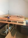
IMG_0506.jpegIMG_0507.jpeg

Note that I’ve added hinges as mentioned earlier to either side of the baseboard joints as belt n braces, as my suspicions of the dreaded warping were eventually realised (they handily come in pairs, however, when popping into a local hardware store for suitable screws to fit, the darned removable pin came away as I alighted my car, dropping unretrievably between the seat runners and the centre console, requiring me to purchase another set……). Heigh Ho.

Current state of play:
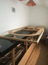
IMG_0508.jpegIMG_0509.jpeg

I agonised over how as I was going to attach the three sided frame to the rear face of the fourth part of the frame which bolts onto the face of the main board. In the end, I simply PVA’d the joints, and have ordered some ‘L’ brackets to bolt them together when the glue has dried.
I’ve placed the top section in place while it dries to keep the frame as flat as possible as, yes, even the PAR is twisted slightly.

The price of wood increases, while the quality decreases it seems. I wonder what the coefficient is for that……………

Thanks for looking,

jonte
 

Phil O

Western Thunderer
Jonte,

You need some vertical stiffeners under the curved trackbed otherwise it will sag. On our club exhibition layouts, we used 2 inch wide 6mm thick stripes, glued on edge more or less down the centre-line to stiffen the trackbed.
 

jonte

Western Thunderer
Jonte,

You need some vertical stiffeners under the curved trackbed otherwise it will sag. On our club exhibition layouts, we used 2 inch wide 6mm thick stripes, glued on edge more or less down the centre-line to stiffen the trackbed.

Hi Phil, and thanks for your interest.

In the photos above, the ‘top’ is just placed to provide weight to ensure that the ‘twisted’ lengths of PAR were as ‘flat’ to the horizontal as I could make them (all the wood to date has been anything but true :( ) while attaching the three sided frame to its fourth side which bolts onto the middle board.

Since completion of the outside of the frame as mentioned, I have continued to work with the curved ‘top’ in place for the same reason whilst the crossmembers were being measured, cut and screwed in place with the vertical stiffeners (or stanchions, as I’ve been calling them) attached at salient points as can be seen previously. The crossmembers are roughly twelve or so inches apart, and like the main middle board which Ive since been using as a makeshift bench, will be supplemented with short longitudinal sections in between in an attempt to thwart any future warping which may occur.

Incidentally, I’ll be leaving a millimetre gap between adjoining track bed sections (the points at which each section of board meet) to allow for possible expansion in warmer weather, although fingers crossed, I’m hoping my over-engineering methods will prevent this from happening; but of course, we all know about Sod’s Law :rolleyes:

Cheers for now, Phil, and thanks again.

Jon
 

jonte

Western Thunderer
Just a couple to show the cross beams in place with uprights (stanchions) attached:

IMG_0516.jpegIMG_0515.jpeg


Stiffeners will be cut and set between the crossmembers, with extra uprights attached where needed.

Incidentally, I’ve gone through the uprights like wildfire, having cut between forty and fifty (from memory), so it’s out with the mitre saw again to cut a load more…….

As a postscript, I have to admit that building baseboards is okay but fast becoming a chore, and I almost yearn for a spot of modelling.

So, for a slight and temporary change in post, here’s something I purchased for not much more than a fiver from an online auction site over the summer:

IMG_2484.jpeg

‘tis the erstwhile Peco modern signal box which I purchased simply for the windows, as turned upside down, they closely resemble those of the concrete signal box at Waterloo, which stood from the early thirties, and which will be my ‘based-on’ for this subject.

To that end, whenever I come across the odd photo of the old Waterloo box, I stash it away for reference. Indeed, I recently found an aerial one which shows the roadside and roof parts, which will come in handy, especially for weathering purposes.

Anyway, back to the woodwork.

jonte
 

Lyndhurstman

Western Thunderer
That's some lovely tree fettling there, Jon. There's something about a nice square joint (of the non-smoking variety, of course :D)

Cheers

Jan
 

jonte

Western Thunderer
That's some lovely tree fettling there, Jon. There's something about a nice square joint (of the non-smoking variety, of course :D)

Cheers

Jan

And they say the camera never lies :oops: Most kind of you to say so anyway, Jan.

To be honest, with all this heaving round woodwork which gets heavier by the day, a ‘joint’ or two might just help my aching ‘joints’ (or so I’m led to believe ;)).

Thanks for your continued interest in my bodging.

Jon
 
Two down, one to go. New

jonte

Western Thunderer
Pleased to report that the second of a total of three baseboards is complete, apart from countersinking the screw heads in the track base which will be completed when glue has dried.

The base shown complete and just needs the track bed attaching:

IMG_0527.jpeg

‘Two become One’ (Moira Anderson), assisted by bolts and removable hinges both sides:

IMG_0528.jpeg

The tracked goes on:


IMG_0534.jpegIMG_0531.jpeg

Not a bad fit, even if I say so myself, for somebody of extremely limited handyman skills:

IMG_0532.jpegIMG_0533.jpeg

Another henge-like appearance:

IMG_0535.jpeg

Tomorrow I’ll order yet more wood for the final push.

Frankly, it won’t be the last order either: so far, I’ve struggled with regard to access, and it’s only now at this point of construction, I realise that better access is required, both to aid future construction and maintaining the layout when finished. Consequently, the intention simply to extend the existing bench ain’t gonna cut the mustard, so a total removal is now planned once the third board is completed, to created a bench which is situated centrally along the available space so that both sides can be accessed a little more easily. Will still be a squeeze, but far better than the current situation.

This was realised when I to clamber onto and over the baseboards (yet again) to insert the removable pin into the split hinge that connects the two boards, on the far side. To say my patience is wearing thin……….

Still, pleased that yet more progress has been achieved, and more importantly, it seems to fit the bill.

So on that lighter note, thanks for your interest and likes.

jonte
 

jonte

Western Thunderer
Thank you, Alan.

Indeed, these boards are quickly becoming a leviathan.

However, I like to think of this embryonic project as more of a traditional permanent layout (despite occasionally ribbing my son and son in law about having to lump it up their tight attic staircases, which never fail to prompt looks of contempt…….).

Thinking of my own childhood, I was determined- with my limited skill set - to iron out as many as possible of those annoying little mishaps such as derailments due to saggy baseboards or poorly laid track, and what you see hopefully goes some way to addressing these foibles.

I can understand the reader reaching the conclusion that this is intended to be portable, but the separate baseboard and connections are merely coincidental, and are there to ease removal once, and inevitably, the children’s interest starts to wane, whence the whole layout will face its ultimate fate in the form of a (hired) chainsaw.

The bright side to this will be that I get my modelling room back for that scale layout I’ve been promising myself.

Let’s just hope Templot is still around.

Best,

Jon
 

jonte

Western Thunderer
Classy carpentry, carefully calculated, competently constructed.

Roger :thumbs:
(Well, what did you expect from me, Jon? ;))

I fear wordsmith wizardry and rhetorical devices - to say nothing of your kind praise, Roger - is rather wasted on me.

See what I mean?

I’ll grab me proverbial weather proofs……….. :))

Cheers,

Jon
 

Phil O

Western Thunderer
Thank you, Alan.

Indeed, these boards are quickly becoming a leviathan.

However, I like to think of this embryonic project as more of a traditional permanent layout (despite occasionally ribbing my son and son in law about having to lump it up their tight attic staircases, which never fail to prompt looks of contempt…….).

Thinking of my own childhood, I was determined- with my limited skill set - to iron out as many as possible of those annoying little mishaps such as derailments due to saggy baseboards or poorly laid track, and what you see hopefully goes some way to addressing these foibles.

I can understand the reader reaching the conclusion that this is intended to be portable, but the separate baseboard and connections are merely coincidental, and are there to ease removal once, and inevitably, the children’s interest starts to wane, whence the whole layout will face its ultimate fate in the form of a (hired) chainsaw.

The bright side to this will be that I get my modelling room back for that scale layout I’ve been promising myself.

Let’s just hope Templot is still around.

Best,

Jon

Hi Jon,

Templot is not likely to disappear any time soon.
 

jonte

Western Thunderer
Hi Jon,

Templot is not likely to disappear any time soon.

Thanks, Phil.

Red Wharf Bay and Benllech in P4 remains a goal; S7 would be good, but space probably wouldn’t permit, and even so, I’m not sure whether a kit for a Webb Coal Tank or 2-4-2T exists in this scale.

I think London Road would be the go-to here.

Cheers,

Jon
 
Top