TFW’s workshop

Tim Watson

Western Thunderer
That is interesting - a 3 position upper quadrant signal (with a rule 55 track circuit indicator) amid all the the lower quadrant signals.

Then into a rabbit hole as I initially thought it would be a Westinghouse product. This signal was produced by the British Power Railway Signal Company Ltd which was a division of GD Peters and Co. Turns out they also provided 3 position ground shunt signals for the SECR at Victoria.
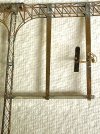
There was an intermediate re-signalling at KX & BI in 1922. The colour light signalling scheme was a 1930s development. One would presume that the alternative banner sign would say ‘MAIN’. I can’t see our Pullman train going into the ‘LOCAL’ platforms.

Tim
 

Tim Watson

Western Thunderer
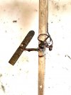
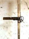
After a bit of fiddling there is now a working somersault signal on the Belle Isle Down signal bridge on CF. There will be another arm working (these two signal a conflicting route) and the other 6-8 can be in fixed positions. I’ll try and take construction photos when the next one is being made.
IMG_9655.jpg
The signal arm was chemically blackened to prevent it being soldered solid.
IMG_9652.jpg
The video shows it simply being pulled on its connecting rodding. There will need to be some cranks and linkages across the bridge to activate it.

Tim
 

Tim Watson

Western Thunderer
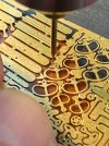
Mick Nicholson has sent me this fascinating MRN article from 1935.
IMG_9658.jpg
For our younger readers, here is a comparison picture of a current £1 coin compared to the half-crown (12.5p in ‘new’ money).
IMG_9659.jpg

A little bit bigger than T gauge, but a very, very small prototype.

Tim
 
Last edited:

John_B

Active Member
Mick Nicholson has sent me this fascinating MRN article from 1935.
That's fascinating. I've got a still unfinished EM version of AR Walkley's "OO Gauge Portable Goods Yard" that I think I was writing up on RMweb rather a long time ago, although I suppose the photos will be long gone. It's interesting to see what he was up to 10 years later.
 

James Spooner

Western Thunderer
That’s fascinating and what is even more so, reading the article, is that the whole thing, including motor and gears, were created from scratch. Truly watchmaking!

Nigel
 

Tim Watson

Western Thunderer
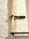
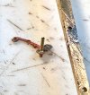
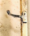
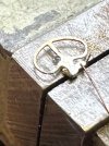
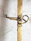
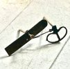
As mentioned previously, I have taken some photos of the fabrication of the second somersault signal. The main components come from MSE (Wizard Models). The etch doesn’t quite manage the holes for the operating linkage so these were drilled out 0.2mm for the linkage and 0.3mm for the pivot.
IMG_9660.jpg

The signal arm bracket requires a bit of work to help locate it on the doll. Working on the principle that it easier to drill a long 0.5mm hole through the doll rather than 0.3mm, the bracket was bushed with a length of Albion Alloys brass tube, OD 0.5mm, ID 0.3mm. This then acts as the pivot for the spectacle and back blind. The far end of the bracket also needed building out with a washer. These components were located in a vermiculite block using pins and soldered together.
IMG_9661.jpg

The pivot bush makes it easy to locate the bracket on the doll.

IMG_9664.jpg
Once in place, the front face of the pivot on the bracket was filed flush, as the spectacle has to work behind the signal arm.IMG_9666.jpg

The spectacle was soldered to some 0.3mm brass rod and filed flush. It was then linked up with a length of thin phosphor bronze wire through the 0.2mm diameter hole in the actuator arm.IMG_9667.jpg

The PB linkage was bent forward in the position of the application point on the signal arm.IMG_9670.jpg

The three components were then chemically blacked to prevent soldering (but scraped off where the collars / back blind needed to be soldered on.

IMG_9671.jpg

Once on the bracket the pivot pins were retained with a collar and the back blind, which was also used to connect the drive rod.IMG_9672.jpg

IMG_9673.jpg

This arm doesn’t quite pivot as vertically as the other one: the linkage length and pivot relationship is critical, but it is within the normal range. I am jolly glad that I don’t have any more to make as working arms on this signal bridge as my patience and eyes are pretty well exhausted.


Tim
 

Tim Watson

Western Thunderer
The Belle Isle Up signal bridge on Copenhagen Fields is now made. It has been quite an epic to get it built, taking far longer than I thought, but I think it will look the part once painted & installed.
IMG_9835.jpg


Making the linkages for the two working dolls required some pivot bearings for the angle cranks. These were made from some square section brass tube with a hole drilled through it, the top filed away, and then a 45 degree notch also filed into the stock, next to the pivot, almost all the way through. The pivot was then soldered onto the signal bridge, and the handle waggled until it broke away.

The etched crank was chemically blackened to stop it from soldering when the pivot wire was soldered in place. IMG_9781.jpg

The signal posts were mounted onto turned brass cylinders, with the operating wire passing through the centre; again chemically blacked to make sure nothing untoward happened when soldering.
IMG_9801.jpg
Hitherto, I had used a strip of PCB to support the signal under construction; this was replaced by a block of wood to act as a handle with precisely bored holes to locate the brass feet and also to be a drilling guide for the layout. The bottom of the lattice posts were further reinforced by two right angle pieces of brass at the foot. These really stiffened up the base. IMG_9802.jpg
Some of the operating linkages have been simplified or omitted - e.g. only a smattering of balance weights, but the complexity of the overall design makes up for it. The access to one of the lamp-man’s lower landings is conjecture on my part as there is no photographic evidence: but it makes it interesting. IMG_9841.jpg
Once I’ve tried it on the layout a careful spray job will follow. In the meantime, back to more gross modelling. IMG_9829.jpg

Tim
 

Tim Watson

Western Thunderer
A week ago the KX Goods Yard ramp line would have looked like this:
IMG_0494m.jpg
The line to the Caledonian Goods & Coal Yard had been roughed-in with a place holder by Mike Randall about 10 years ago, refined some more in 2016 and incorporated with Matthew Wald’s Goods & Mineral Signal Box in July’ ‘21. It is the final major civil engineering structure to be finished - above ground. I thought it was about time the area was worked-up some more, especially as we are having a photo shoot on Thursday. Mike’s core was basically sound, but much more detail was needed, with filled-in arches under the ramp and more ‘business’ in the S&T yard. The side walls of the ramp were marked out with a pair of dividers.
IMG_9843.jpg
The arches were scribed-in and then the centre part cut out. The arch ring was paired away with a #15 scalpel plate to give a guide line for painting.
IMG_9850.jpg
The structure was further refined and string brick courses and capping added. The arch infill pieces were thinned down so that there was a slight height difference with the arch spandrel.
IMG_9859.jpg
A new 1mm thick ply track bed was made and the track laid directly on to this: the base being screwed down to the ply sub-structure with 1/8” ~1 wood screws. 1000014307.jpg
The goods yard now looks much bigger than it did: a strange effect, really, whilst the S&T yard has acquired some signal bits and extra buildings from the old Hill End layout. Signals are being made, indeed the Down Goods gantry to the south of Copenhagen Tunnel can just be glimpsed in the background, being made by Peter Chapell. Finally a bit of an arty shot with some early morning mist in the yard. IMG_9871.jpg[/URL

A busy week…
Tim
 
Last edited:

timbowales

Western Thunderer
Tim, regarding the way that you've posed the arms, speaking as a retired signalling engineer, I would not expect the lower distant arm to be showing a proceed aspect whilst the upper stop arm was "on"?
Tim T
 

timbowales

Western Thunderer
Well done, Tim W
One annoying Apple feature about an iPad is that I can't insert emojis. If I were doing this on my iPhone at this point I would be able to insert a " thumbs up" emoji, but I can't
Tim T
 

daifly

Western Thunderer
:thumbs: From my iPad. :mad::confused::p:D:eek::mad::(;):rant::bowdown:
Dave
Ps first click on the post toolbar square brackets on the right. That ‘unlocks’ the various submenus etc.:thumbs:
 
Top