The Heybridge Railway, 1889 to 1913

Ian@StEnochs

Western Thunderer
Herbie I could not ask for a more useful photo of the cab interior. I expected to find 564 at Weybourne shed last August but she was in steam with a busy crew and this shot wasn't possible. I am treating the cab interior as a separate model to do after the rest of the model is built and painted and if you have other footplate shots you could append them to the Gallery topic, this had been more popular than I expected:

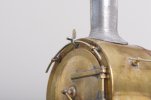
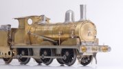
Prototype - Ex-GER Y14 (LNER J15) preserved at the North Norfolk Railway

Back to the build, yesterday's efforts are getting down into the noise floor but they have to be done. I have stripped out all of the electrics and dealt with most of the missing details on the tender . . .

- -

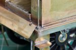
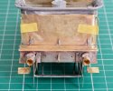
Rear handrails.View attachment 182555
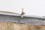
The original rear handrails (last October) broke off a couple of times so I have tried for a stronger fixing. This is microbore brass tube by Albion Alloys, 1.1 mm OD and 0.9mm ID fixed into the body with 188 degree solder paint.

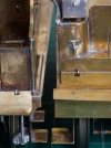
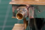
View attachment 182556
Then trimmed flush to make a socket.

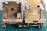
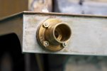
View attachment 182557
The handrail wire is 0.7 mm diameter so there is room for the glue to hold them into their sockets after painting.

Good solution Richard. I do similar as most of my locos have bright metal handrails. I try to solder the tube from the inside before fitting the top. I have been using 1/0.5 tube and open the bore out once soldered in. A lot of handrails had a boss which butts up against the plate with a nut and washer on the other side. If the tube is left slightly proud it represents that boss.

Ian.
 

Richard Gawler

Western Thunderer
Good solution Richard. I do similar as most of my locos have bright metal handrails. I try to solder the tube from the inside before fitting the top. I have been using 1/0.5 tube and open the bore out once soldered in. A lot of handrails had a boss which butts up against the plate with a nut and washer on the other side. If the tube is left slightly proud it represents that boss.

Ian.

Yes, I would try to add the tubes and solder them up from the inside next time, when the access is there.

On the bright side, the 1.1 mm tube has a circumference 50% bigger than 0.7 mm wire, so working from the outside I should have ended up with enough solder to make a usefully stronger joint. .
 
Last edited:

Richard Gawler

Western Thunderer
Cab handrails, revisited.

I am sure there is an inverse relationship between my quantity of photgraphs and my progress. I suppose, construction has reduced to snagging.

DSC_2334.jpg
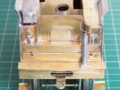
The cab handrails have come adrift three times in as many months. This is not a particularly elegant solution but they are supposed to butt onto the top of the footplate and this isn't strong enough. Two holes in the footplate would be good but I dare not try to get them in the right location with so much detail nearby so I have settled for some 14 BA nuts. The nuts provide four times the contact area and don’t look terribly out of place at a normal viewing distance. If I was starting again I would drill some holes while the footplate was in its original state with nothing attached to it.

DSC_2347.jpg
The handrails opposite, on the tender, are even harder. I have fitted the locker doors (October last year) most of a millimetre too far outwards and there is no space to add the handrail brackets. The doors are half-etched, soldered over their entire backs, and locked into place with their wire handles. They are also very close to the flare castings.

The bottom ends of these handrails will have to be a loose fit into the tender footplate to let me dismantle the tender and get at the control gear. I will leave them off altogether.

DSC_2345.jpg
A view of the cab and tender for completeness. Blu Tack holding the long handrails. Barrel distortion from lens evident, the handrails are straighter than this.

I had trouble with the cab handrails on Nellie the crane tank. They needed a lot more more thought, much earlier in the build.

DSC_2342.jpg
The brake standard was slightly skew and I tried to straighten it with fingers. Stupid, too much leverage, this stripped the screw thread inside it (a week ago). Maybe Fate is telling me I really need to stop. I glued a 10BA stud into the standard and fixed it onto the footplate with a nut and washer underneath. Double thickness coupling link, unused hole blanked off and will be hidden by the drop-in footplate extension.

I am now stuck for parts to try to add the studs on the Markits buffers. Probably do me good to put everything to one side for a few days.
 
Last edited:

Richard Gawler

Western Thunderer
Tender lamp irons and buffer fixings.

DSC_2366.jpg
I have put the lamp irons from the kit onto the back of the tender. I find this pleasantly doable using solder paint and a micro flame torch (as here) and nigh impossible using solder wire and an iron.

The buffer fixings are M0.8 nuts from Prime Miniatures jammed onto 0.7mm wire to represent the studs. I tried a 16BA nut but it looked overscale. This task turned out to be easier than I expected - it is easy to shove a length of wire into a nut and then the wire gives a handle to hold it with.
 
Last edited:

Richard Gawler

Western Thunderer
DSC_2373.jpg
I have cleaned up the buffers with the mildest plastic flap wheel in my collection. This dislodged three of the studs (out of the total from both buffers), two were lost onto the carpet so I made new ones. Then I tried my favoured Cyanoacrylate but this did not work, though the problem might be residual flux lingering inside the buffer stock.

I can see, future iterations might bring more improvements and will definitely bring more losses, so I am stopping now while I still have enough parts to do the loco buffers.
 
Last edited:

Richard Gawler

Western Thunderer
Studs on loco buffers, and the two final lamp irons.

DSC_2381.jpg
The studs on the loco buffers are the same 0.7 mm wire and M0.8 nuts, but fixed this time with epoxy glue. Rather wasteful of glue because I had to mix far more than I used, but no cleaning up afterwards. I used nickel silver wire because it is brighter than brass and gives more contrast to help seeing the job.

DSC_2389.jpg
The lamp iron at the top is the last part to go onto the loco before painting. This is same etch as the tender lamp irons, but with the bottom lug wrapped under the handrail.

DSC_2380.jpg
Finally, the lamp iron at the top of the tender. I soldered this on by tinning both iron and flare with 188 degree solder and sweating them together (be quick!), and then filled in around the joint with 100 degree solder. This is the strongest way I can think of to make the joint.

This completes my build of the Y14 and its S23 tender before painting.
 
. . completed loco and tender and takeaways

Richard Gawler

Western Thunderer
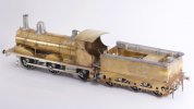
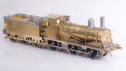
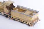
This is my Y14 with its S23 tender ready for painting:drool:

The clack valves and buffer heads are resting loose in position and I have removed the motor and all of the electrics. The tender springs and axleboxes will go on after lining. This loco has been my project for the winter of 2022/23, and I am so glad I have had a go at this kit.

DSC_2397.jpg

DSC_2394.jpg

DSC_2400.jpg

DSC_2393.jpg
 

Richard Gawler

Western Thunderer
Takeaways from the build of the kit.

For my Heybridge Railway, the Y14 currently consumes over a third of my workbench topic while representing just a token visiting engine from the neighbouring GER. A bit out of proportion really. To wrap up the Y14 for now, here are my takeways from building the Connoisseur Models kit which I think are putting together in one place, to help those wanting to build the same kit.

Most of the work to build a Y14 instead of a J15 involved omitting parts supplied in the kit and filling in unwanted holes. The new parts I made or bought were a smokebox door, blower valve, lubricator and cab roof. I also worked up the bifurcated part of the reverser reach rod where it meets the front of the cab. I omitted many parts from the kit, including the loco brakes and the cab roof, so I can only comment on the parts I used . . .
Screenshot 2023-03-14 14.36.17.jpg
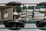
(1) Starting with the chassis, the kit sets the brass rod (A) too far away from the pivot for the reverser (B). I adjusted the holes in the frames to move (A) forwards about 0.7 mm, to get the inside motion to fit. Later I realised the reach rod for the reverser is about 0.5 mm too short at the cab end so it might be better to move the pivot (B) or possibly its fold-up brackets backwards instead.
motor location composite.jpg
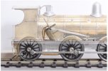
(2) I moved the front of the firebox backwards about 2 mm and built up the underneath of the boiler to fill the gap created. This lets the boiler band here wrap under the boiler and it doesn’t run down the sides of the firebox. The photo composite shows, I got away with it. This image also shows there is room for a small flywheel, but in the end I omitted mine because it doesn't do anything useful with battery power.

(3) With the drive to the middle axle, it is tricky to put any sideplay here unless you arrange a floating gearbox or accept premature wear on the worm gear. Adding a little sideplay will let the loco negotiate a Setrack point. HOWEVER, if I wanted to use a Setrack curve I would need a longer coupling bar between loco and tender. This would rather spoil the look of the model. So, with no sideplay on any axles and the loco and tender a scale distance apart, I have a model which negotiates a 4ft 6in radius curve (at 32 mm gauge), but not a 3ft 5in one. This should be fine for any take on a scenic layout.
DSC_1604.jpg
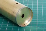
(4) The intended arrangement of the boiler front makes for quite a difficult assembly onto the smokebox. It also gave me a catastrophic disassembly. I filed down the edges of the boiler front and put it about 5 mm inside the front of the boiler. This greatly reduces the amount of metal to be joined or dismantled when adding the smokebox.

And this is all.

But having built a kit supplied in five frets, I think it is incredible to see such complex assemblies go together so well when the parts were drawn by hand. Really, the kit went together like a dream. But then, everyone says Jim’s kits do this.
 

Chas Levin

Western Thunderer
Nice work Richard, nice composite picture too - I hadn't thought of doing something like that and varying the opacity of an upper layer to look at how a gearbox and motor fit inside a loco body.

One question: in your first picture in this post, you have what appears to be a curved piece of NS curving round the gear wheel and attached at one end to the motor mount. Am I right in assuming that it a) stops the motor mount rotating, b) protects the gear against foreign objects and c) hides the un-prototypical gear teeth from view?

If so, that's a terrific idea which I shall try and incorporate in future builds...
 

Richard Gawler

Western Thunderer
Yes the curvy bit of metal is my attempt to hide the teeth of the worm gear. It was a late addition to the chassis after I realised I had made the effort to provide the correct area of daylight in front of the firebox and all I could now see was the shiny teeth of the gear.

See: The Heybridge Railway, 1889 to 1913

The composite picture is from the only photos of the model using a tripod. Everything else is hand-held, the indoor ones are using my antediluvian but punchy Photax flash head and a silver brolly from Jessops which is very nearly as old.
 
Last edited:
Stationary boiler revisited . . making the model more prototypical

Phil O

Western Thunderer
View attachment 182486
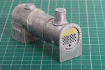
I have had a bit of a culture shock going from brass to whitemetal - assembly of the boiler has been spread over four days of sessions with solder, glue, filler and more glue. The sides of the firebox are the perfect shape to fit the backhead but they stop most of 3 mm apart.

I put the model above my eye level for the glue to cure . . . the fitting on the top of the firebox ended up twisted so I filed off the nut and stud detail, I would rather have no detail than wrong detail. I will try to remember to blend this into the firebox the next time I mix up some Milliput.

View attachment 182487
The steam outlet could go onto either ring of the boiler, I chose the forward one to try for a slightly more Victorian look.

I suspect this model will look a whole lot better with a coat of paint to bring the various surfaces together. This could be months away so I have plenty of time to find out whether the Lomac is a suitable wagon to carry it and how the chains should go.

Hi Richard,

The front tube plate of the boiler on the well wagon is somewhat strange, to my professional eye, boilermaker rtd.

The tubes should end two or three rows lower, otherwise the firebox crown plate will be up against the wrapper. The firebox crown plate is usually around 6 inches above the top row of tubes, the tubes only tend to be about half way up the barrel.
 

Richard Gawler

Western Thunderer
Hi Richard,

The front tube plate of the boiler on the well wagon is somewhat strange, to my professional eye, boilermaker rtd.

The tubes should end two or three rows lower, otherwise the firebox crown plate will be up against the wrapper. The firebox crown plate is usually around 6 inches above the top row of tubes, the tubes only tend to be about half way up the barrel.
Hi Phil,

Well - when I did a Google image search for "boiler tube plate" the very first result was exactly as you describe.

DSC_2411.jpg
Supposing I fill in the top three rows of holes the remaining holes will look like this. Does this look about right?
 

simond

Western Thunderer
It does, imo.

I’d bow to Phil’s experience, but I’d be adding a pipe & flange or two to get the steam out when it’s installed.

such flanges would typically have a wooden blanking plate bolted on to keep rubbish (and squirrels) out.
 

simond

Western Thunderer
I suggest filling the fourth row (of 4 holes) as well.
Look on t’other end. Lower water gauge fitting should be more or less level with top row of tubes. (There would be wooden blanks on all these holes too)

I guess the rivets along the sides might be stay ends too, which would also be about the same height.
 

Phil O

Western Thunderer
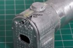
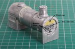
As Brian has suggested, I would remove the next row of tubes, too. You could add the nuts for the longitudinal stays, to match those on the back head, the horizontal row of 4 nuts. You could also add the washout plugs. The steam pipe would go on the centre line at the top, this would be about 6 inches in diameter and the flange would be about 2 or three inches in front of the tube plate to allow fitting the nuts, when the T piece was bolted on. All tube holes would have wooden bungs in and a blank over the steam pipe, we used a bit of hardboard and a couple of bolts to hold it in place. I have added some notes to your pictures.

boiler backhead.jpg


front tube plate.jpg
 
Last edited:

Phil O

Western Thunderer
Not had to use 3 inch plate. I have flanged and rolled 1 inch plate for valve boxes. We had a 20 ton overhead crane to hold the plate.
 
Top