You don't fit the cylinder wrappers to the former..it works!Hi Peter,
If the valence is fixed to the footplate, and the cylinder wrappers are fixed to the cylinder former and the cylinder former is fixed to the chassis, how do you get inside?
Confused of Folkestone
You are using an out of date browser. It may not display this or other websites correctly.
You should upgrade or use an alternative browser.
You should upgrade or use an alternative browser.
P A D
Western Thunderer
Just go to the F7 stand at the next show and those unscrupulous traders will force you to buy their wares. You know what these kit purveyors are like!Makes me want to build another one!
")
Hi Peter,
If the valence is fixed to the footplate, and the cylinder wrappers are fixed to the cylinder former and the cylinder former is fixed to the chassis, how do you get inside?
Confused of Folkestone
Sorry, I did not explain it very well, but David is correct. The wrappers are only bent to the shape of the cylinder frame, not soldered to it. The chassis with the cylinders is inserted between the wrappers and then the rear end is lowered to the bottom of the cab floor, then fixed with 4 screws. To get it out after removing the screws, you lift the rear end slide back and lift. These should clarify how it works.


Cheers,
Peter
P A D
Western Thunderer
Thanks both.
now less confused!
cheers
Simon
Hi Simon,
By less confused, do you mean something is still not clear? If so please let me know and I will try to clarify.
Cheers,
Petet
")
P A D
Western Thunderer
Next up the cab roof.
It is made up on a fold up jig that is cut away and discarded when complete. Here's the first stage with the main roof etch rolled and soldered in place.

From the underside you can see the detail overlay on the inside.

And after completion.

For a cab roof it's quite complex being made from 14 pieces.

Here it is on the cab.
At the front end I have now epoxied the chimney in place. First I marked the position of the hole for the whistle on the casing. I then drilled through 0.8mm and inserted a short length of rod to act as a locator for the chimney. Here it is placed on the casing.

With the chimney held in place I marked the perimeter in pencil.

I marked the centre of the chimney holes in the casing and drilled through. I then scored the resin inside the pencil outline and on the undeside of the chimney casting to aid adhesions of the epoxy. Both were cleaned with cellulose thinners before gluing the chimney in place. When it was part set, I pulled the locating rod out from the underside.
Here's the chimney after the adhesive had cured.


The handrails have also been made but are only push fit in the holes for now to facilitate painting and lining. The same goes for the ejector exhaust and the pipe. Finally, the inspection covers and handles have been added .

There appears to be a kink in the handrail but I think that's just because the knob is not fully pushed into the hole.

Here's a view with the tender.

And from the front.
Cheers,
Peter
It is made up on a fold up jig that is cut away and discarded when complete. Here's the first stage with the main roof etch rolled and soldered in place.
From the underside you can see the detail overlay on the inside.
And after completion.
For a cab roof it's quite complex being made from 14 pieces.
Here it is on the cab.
At the front end I have now epoxied the chimney in place. First I marked the position of the hole for the whistle on the casing. I then drilled through 0.8mm and inserted a short length of rod to act as a locator for the chimney. Here it is placed on the casing.
With the chimney held in place I marked the perimeter in pencil.
I marked the centre of the chimney holes in the casing and drilled through. I then scored the resin inside the pencil outline and on the undeside of the chimney casting to aid adhesions of the epoxy. Both were cleaned with cellulose thinners before gluing the chimney in place. When it was part set, I pulled the locating rod out from the underside.
Here's the chimney after the adhesive had cured.
The handrails have also been made but are only push fit in the holes for now to facilitate painting and lining. The same goes for the ejector exhaust and the pipe. Finally, the inspection covers and handles have been added .
There appears to be a kink in the handrail but I think that's just because the knob is not fully pushed into the hole.
Here's a view with the tender.
And from the front.
Cheers,
Peter
Last edited:
Dan Randall
Western Thunderer
Nice work Peter.  It seems to be going together rather rapidly!
Regards
Dan
It seems to be going together rather rapidly!Regards
Dan
P A D
Western Thunderer
Got the lamp irons on this afternoon.


And sorted out the kink in the left side handrail. The 1st and 3rd knobs weren't at 90 degrees to the casing, but with a touch of the iron and a little finger pressure on the rail, they sprang into place. The ejector exhaust pipe still needs the brackets fitting.

Apart from the substantial time saving and fidelity that the resin casting brings, it also doesn't tarnish. Having built the JLTRT 57XX, I prefer the neutral ivory colour of the Finney resin to the bright blue. Still it makes no difference once the paint's on.

Here's a view into the cab with the roof on. The screws will remain in place as the cab is not glued to the resin, but they will of course be hidden by the back plate casting.

Cheers,
Peter
And sorted out the kink in the left side handrail. The 1st and 3rd knobs weren't at 90 degrees to the casing, but with a touch of the iron and a little finger pressure on the rail, they sprang into place. The ejector exhaust pipe still needs the brackets fitting.
Apart from the substantial time saving and fidelity that the resin casting brings, it also doesn't tarnish. Having built the JLTRT 57XX, I prefer the neutral ivory colour of the Finney resin to the bright blue. Still it makes no difference once the paint's on.
Here's a view into the cab with the roof on. The screws will remain in place as the cab is not glued to the resin, but they will of course be hidden by the back plate casting.
Cheers,
Peter
P A D
Western Thunderer
First up tonight was a correction to the tender. I noticed in recent photos that the beading on the right hand side appeared to be higher at the rear. I checked it with a pair of dividers and sure enough it was, so I unsoldered it and re did it.

Next, the brackets for the ejector pipe, which are simple wrap around etchings.

And fitted.

The brackets are just pushed into the holes and will be removed for painting. Which reminds me, I must solder them to the pipe.

Here we have the pipe and valve thingy below the ejector pipe. The instructions call it an anti carbonising valve, but j understood it was something to do with the whistle.

Either way it's on (push fit only) as are the buffers.
Again, the whistle is just push fit.

I forgot to mention it before, but I've modified the rear of the chimney casing to represent the shape as fitted by BR. Here's an extract from the Isinglass drawing which shows the difference compared to the original LNER variant.

The safety valves have also been temporarily fitted with a drop of superglue, as has the roof to protect the overhangs on the cab sides.


And finally, I have added the covers on the casing where the wash out plugs were later added to the fire box sloping edges. These are not provided in the kit and are spares from another kit.


Cheers,
Peter
Next, the brackets for the ejector pipe, which are simple wrap around etchings.
And fitted.
The brackets are just pushed into the holes and will be removed for painting. Which reminds me, I must solder them to the pipe.
Here we have the pipe and valve thingy below the ejector pipe. The instructions call it an anti carbonising valve, but j understood it was something to do with the whistle.
Either way it's on (push fit only) as are the buffers.
Again, the whistle is just push fit.
I forgot to mention it before, but I've modified the rear of the chimney casing to represent the shape as fitted by BR. Here's an extract from the Isinglass drawing which shows the difference compared to the original LNER variant.
The safety valves have also been temporarily fitted with a drop of superglue, as has the roof to protect the overhangs on the cab sides.
And finally, I have added the covers on the casing where the wash out plugs were later added to the fire box sloping edges. These are not provided in the kit and are spares from another kit.
Cheers,
Peter
P A D
Western Thunderer
Some further work on decorating the body before moving back to the chassis. First I soldered the fixing brackets to the ejector pipe. Here it is after removal for cleaning up.

The small inspection door in front of the 1st boiler band had a moulded handle on the resin casting. I centre popped it and drilled through 0.5mm. I then added a small rivet fixed with super glue, but not pushed all the way home, to represent the handle.

When the resin boiler casing was glued to the brass running plate, there was a gap on the left hand side between the bottom edge of the casting and the etch beading. This was due to an inward bow in the casting , not much but enough to show. I have filled it with some cellulose filler and rubbed down. After painting it won't show.
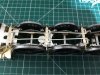
Moving back to the chassis, the front driving wheel compensation needed some attention. This axle pivots on a length of steel rod, whilst the middle and rear axles are on beams. I noticed that the loco appeared to be nose diving and this was due to a slight bend in the rod. Easy to correct, but I don't think it's strong enough to stand the test of time, so I added a strengthener/adjuster to take up any wear that may occur. You can see the rod extending from the spacer behind the front sandboxes. I have added a spacer over the horn box made from a laminate of waste etch. This has been drilled and tapped 8BA and a screw and lock nut inserted. The ride height was then corrected with the screw and locked in place with the nut.

And looking from the rear forwards.

I have been putting off adding the front buffer beam as the dummy spring castings were missing. I sent a mail to F7, but I know the chaps have day jobs and as yet I have not received them. Being an impatient sod, I thought " are we not men?", just make some. So, after coiling and soldering some 0.6mm copper wire, and fiddling about with some bits of brass tube and 16BA bolts and nuts, we have this. That's a picture of the missing castings behinds the buffer beam.

Here's the beam soldered to the frames. There was quite a gap in the slots above the beam, so I added some waste etch either side, rather than just trying to bridge it with solder. When the buffers are compressed the 14BA nut passes into the coil. It would be nice by the way, if other kit makers dispensed with the 8BA fastenings on buffers and went with smaller nuts which are less obtrusive, or in this case hidden.
Here's what they look like with the body on.
And t'other side.

The cartazzi truck also received some further attention to the springing. After getting the heads up from Richard Lambert on how he changed from a single central spring, to two side springs on his A3 to improve the performance on the curves, I did the same on the A4. Having tested the chassis on my brother's railway, if works a treat. However, the NS wire didn't cut the mustard, being not resilient enough, so I replaced it with steel wire. To fit it to the inner frames I first soldered some brass tube in place, into which the steel wire can be inserted. For now they are just loose, but after painting, a drop of super glue will keep them in place. To reduce friction and achieve free side to side movement, all the sliding surfaces have been highly polished. This is after fitting the tube and steel wire. The wire has subsequently been polished and oiled.

And with the slider in place before polishing. In this condition it would not slide under it's own weight. After polishing and oiling it moves freely. The dummy cartazzi axle box keeps have also been added.

The mud hole covers, wash out plugs and blow down tap have also been added to the lower firebox.


And a couple of broadsides with the tender.


Cheers,
Peter
The small inspection door in front of the 1st boiler band had a moulded handle on the resin casting. I centre popped it and drilled through 0.5mm. I then added a small rivet fixed with super glue, but not pushed all the way home, to represent the handle.
When the resin boiler casing was glued to the brass running plate, there was a gap on the left hand side between the bottom edge of the casting and the etch beading. This was due to an inward bow in the casting , not much but enough to show. I have filled it with some cellulose filler and rubbed down. After painting it won't show.
Moving back to the chassis, the front driving wheel compensation needed some attention. This axle pivots on a length of steel rod, whilst the middle and rear axles are on beams. I noticed that the loco appeared to be nose diving and this was due to a slight bend in the rod. Easy to correct, but I don't think it's strong enough to stand the test of time, so I added a strengthener/adjuster to take up any wear that may occur. You can see the rod extending from the spacer behind the front sandboxes. I have added a spacer over the horn box made from a laminate of waste etch. This has been drilled and tapped 8BA and a screw and lock nut inserted. The ride height was then corrected with the screw and locked in place with the nut.
And looking from the rear forwards.
I have been putting off adding the front buffer beam as the dummy spring castings were missing. I sent a mail to F7, but I know the chaps have day jobs and as yet I have not received them. Being an impatient sod, I thought " are we not men?", just make some. So, after coiling and soldering some 0.6mm copper wire, and fiddling about with some bits of brass tube and 16BA bolts and nuts, we have this. That's a picture of the missing castings behinds the buffer beam.
Here's the beam soldered to the frames. There was quite a gap in the slots above the beam, so I added some waste etch either side, rather than just trying to bridge it with solder. When the buffers are compressed the 14BA nut passes into the coil. It would be nice by the way, if other kit makers dispensed with the 8BA fastenings on buffers and went with smaller nuts which are less obtrusive, or in this case hidden.
Here's what they look like with the body on.
And t'other side.
The cartazzi truck also received some further attention to the springing. After getting the heads up from Richard Lambert on how he changed from a single central spring, to two side springs on his A3 to improve the performance on the curves, I did the same on the A4. Having tested the chassis on my brother's railway, if works a treat. However, the NS wire didn't cut the mustard, being not resilient enough, so I replaced it with steel wire. To fit it to the inner frames I first soldered some brass tube in place, into which the steel wire can be inserted. For now they are just loose, but after painting, a drop of super glue will keep them in place. To reduce friction and achieve free side to side movement, all the sliding surfaces have been highly polished. This is after fitting the tube and steel wire. The wire has subsequently been polished and oiled.
And with the slider in place before polishing. In this condition it would not slide under it's own weight. After polishing and oiling it moves freely. The dummy cartazzi axle box keeps have also been added.
The mud hole covers, wash out plugs and blow down tap have also been added to the lower firebox.
And a couple of broadsides with the tender.
Cheers,
Peter

P A D
Western Thunderer
Made a start on the brake rigging and as with the A3, I'm making some additions to the etchings. The cross beams are made by adding 3 laminates to the main etch which includes pull rods. Bolt detail is represented by half etch rivets, so a bit lacking. The first up is to drill through the rivets on either the main etch of the separate laminates. I've got a small proxxon bench drill now so a lot easier than with the hand held mini drill.

After soldering the cross beams, I then drilled one hole 0.8mm in the front
beam and one in the rear. This allowed the whole ensemble to be pinned to a block of wood with 0.7mm brass rod. Mine's quite new so doesn't have the character of Nick Dunhill's vintage specimen. Once pinned, the rest of the holes were drilled through and short lengths of rod inserted and then soldered. I'd set the depth gauge to about 4mm, but 2mm would have been OK and easier to remove after soldering.

Here it is after soldering the rods. I made a simple gauge from waste etch by drilling a 0.8mm hole that is placed over the rods and after pressing down tight with the side cutters, the excess is snipped off. It gives a consistent length to each. That's the gauge below the wood.

After they rods are all cut, I inverted the wood and then rubbed down the rods on some 400 grit emery paper on a flat surface . The whole ensemble is then removed by prising it away from the wood with a craft knife, then inverted and pushed back into the holes to allow the rods on the other side to be cut to length.

Here it is all done and dusted. This is the upper side, where I have soldered on some suitable strips of waste etch to the top of the pull rods to beef them up. This makes them a bit thick viewed from the side, but I would rather have them robust than prototypically thin and frail.

And from the underside (no joints visible on the pull rods next to the cross beams).
Here it is with the brake hangers and shoes after they were laminated and cleaned up for fitting. The pair on the left are for the rear wheels.
I gave them a quick trial fit before packing up. The support bracket for the running plate just behind the rear wheels, is too close to allow the hanger to be put onto the pivot and needed some attention with a dental burr in the mini drill, to gain some clearance. Better to do that in the flat and I should have known as it was the same on the A3.
And a view from the side. (Yes I know, you shouldn't start a sentence with the word "and", but it's a blog not literature, so apologies for that)

I need to do some checking on clearances before firing up the Antex, so it's all loose at the moment.
Cheers,
Peter
After soldering the cross beams, I then drilled one hole 0.8mm in the front
beam and one in the rear. This allowed the whole ensemble to be pinned to a block of wood with 0.7mm brass rod. Mine's quite new so doesn't have the character of Nick Dunhill's vintage specimen. Once pinned, the rest of the holes were drilled through and short lengths of rod inserted and then soldered. I'd set the depth gauge to about 4mm, but 2mm would have been OK and easier to remove after soldering.
Here it is after soldering the rods. I made a simple gauge from waste etch by drilling a 0.8mm hole that is placed over the rods and after pressing down tight with the side cutters, the excess is snipped off. It gives a consistent length to each. That's the gauge below the wood.
After they rods are all cut, I inverted the wood and then rubbed down the rods on some 400 grit emery paper on a flat surface . The whole ensemble is then removed by prising it away from the wood with a craft knife, then inverted and pushed back into the holes to allow the rods on the other side to be cut to length.
Here it is all done and dusted. This is the upper side, where I have soldered on some suitable strips of waste etch to the top of the pull rods to beef them up. This makes them a bit thick viewed from the side, but I would rather have them robust than prototypically thin and frail.
And from the underside (no joints visible on the pull rods next to the cross beams).
Here it is with the brake hangers and shoes after they were laminated and cleaned up for fitting. The pair on the left are for the rear wheels.
I gave them a quick trial fit before packing up. The support bracket for the running plate just behind the rear wheels, is too close to allow the hanger to be put onto the pivot and needed some attention with a dental burr in the mini drill, to gain some clearance. Better to do that in the flat and I should have known as it was the same on the A3.
And a view from the side. (Yes I know, you shouldn't start a sentence with the word "and", but it's a blog not literature, so apologies for that)
I need to do some checking on clearances before firing up the Antex, so it's all loose at the moment.
Cheers,
Peter
Attachments
P A D
Western Thunderer
Brake rigging completed.

Not easy to see in these images, but again I drilled through the half etch representation of bolt detail at the "joints " and added 0.7 mm rod to represent the fixings.

About 30 parts in all excluding any rods added by me, so not quick to do. The W1 example on the F7 stand at Kettering built by Mickoo, had all the pull rods riveted and the brakes opperated, so hats off to Mick.

I ground the front faces of the shoes to increase clearance, but it may need a smear of epoxy to avoid any shorts when running. The tops pf the brake hanger brakets are not represented, so I will add these from waste etch later.


Cheers,
Peter
Not easy to see in these images, but again I drilled through the half etch representation of bolt detail at the "joints " and added 0.7 mm rod to represent the fixings.
About 30 parts in all excluding any rods added by me, so not quick to do. The W1 example on the F7 stand at Kettering built by Mickoo, had all the pull rods riveted and the brakes opperated, so hats off to Mick.
I ground the front faces of the shoes to increase clearance, but it may need a smear of epoxy to avoid any shorts when running. The tops pf the brake hanger brakets are not represented, so I will add these from waste etch later.
Cheers,
Peter
P A D
Western Thunderer
While adding the steps to the rear frames I decided to beef up the fixing by drilling through he outer rivets on ech step and adding 0.7mm rod through the holes in the frames. The rod was then snipped and rubbed down with a nail buffer to round off the ends. The steps are then lined up on the rods and soldered in place. The rods crossing between the frames at then removed with a slitting disc and the inner faces cleaned up.

The bottom of the firebox is missing the retaining rods and cotter pins so I knocked these up.

The remaining details were also added to complete this area of the build. Here's a low angle view of the lower firebox showing the retaining pins as well as the added detail on the ash pan operating rod bracket. The pin representing the bolts need straightening.

And t'other side showing the axlebox, spring detail and ash pan operating lever.
Again the half etched "bolt" detail at each end has been drilled through and rod added to improve the appearance.

Inside the firebox, the fold leaves a gap where the operating lever bracket fixes.

I covered these gaps by adding small pieces of waste etch, which improved the appearance underneath, but also gives a secure fixing to the ash pan rod which can then be snipped.

And with the radial axle box in place.

Here are the frames after cleaning. Next up will be the slide bars and motion etc.
Some further views of the rear frame details.

Its getting there.

And with the tender.


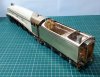
And finally, play time. I couldn't resist seeing what it looked like with the full depth valance, so stuck one side on with bluetac.

Impressive, but better without.
Cheers,
Peter
The bottom of the firebox is missing the retaining rods and cotter pins so I knocked these up.
The remaining details were also added to complete this area of the build. Here's a low angle view of the lower firebox showing the retaining pins as well as the added detail on the ash pan operating rod bracket. The pin representing the bolts need straightening.
And t'other side showing the axlebox, spring detail and ash pan operating lever.
Again the half etched "bolt" detail at each end has been drilled through and rod added to improve the appearance.
Inside the firebox, the fold leaves a gap where the operating lever bracket fixes.
I covered these gaps by adding small pieces of waste etch, which improved the appearance underneath, but also gives a secure fixing to the ash pan rod which can then be snipped.
And with the radial axle box in place.
Here are the frames after cleaning. Next up will be the slide bars and motion etc.
Some further views of the rear frame details.
Its getting there.
And with the tender.
And finally, play time. I couldn't resist seeing what it looked like with the full depth valance, so stuck one side on with bluetac.
Impressive, but better without.
Cheers,
Peter
Attachments
Last edited:
simond
Western Thunderer
I think I agree.
I think the most elegant feature of these most elegant locos is the shear-line of the footplate & valence. There’s something of the racing seaplanes, and of some rather beautiful boats from a rather later era about them. Tramontana springs to mind.
The build is beautiful - another masterclass.
Best
Simon
Rob Pulham
Western Thunderer
Impressive, but better without.
Cheers,
Peter
Sorry Peter, but I have to disagree on that one, personally I think that they look so much better as built but each to their own.
P A D
Western Thunderer
Simon, many thanks.
Rob, absolutely. Each to his own, so I look forward to your W1 build in fully streamlined condition. Might be tempted myself on that one.
Anyway, on with the A4. I made a start on the slide bars and hear are the laminates pinned to a block of wood ready for soldering.

One point to note is that although the cusp does not need filing off before soldering, it's best to remove it from the raised area where the "fins" are. As you can see here, it's much easier to do it this way than after it is all together.

And after soldering.

Here they are after snipping off the excess rod.

And after working on the left hand one with files and wet and dry.
As you can see here, filing between the fins would be very difficult at this stage.

The short extension at the rear is sacrificial and will be sawed off later to fit the cross head.

I made a start on cleaning up the right hand one.

I have also made a start on removing the cusp between the upper and lower bars, first with course grade emery and then with a small file.

I know some prefer cast slide bars, but I think for these 3 bar types, Mr. Finney's etched design gives a better result and an easier method of accurately mounting them on the cylinders. They do take a bit more work though, but hey, are we not men? Or women in Heather's case.
Cheers,
Peter
Rob, absolutely. Each to his own, so I look forward to your W1 build in fully streamlined condition. Might be tempted myself on that one.
Anyway, on with the A4. I made a start on the slide bars and hear are the laminates pinned to a block of wood ready for soldering.
One point to note is that although the cusp does not need filing off before soldering, it's best to remove it from the raised area where the "fins" are. As you can see here, it's much easier to do it this way than after it is all together.
And after soldering.
Here they are after snipping off the excess rod.
And after working on the left hand one with files and wet and dry.
As you can see here, filing between the fins would be very difficult at this stage.
The short extension at the rear is sacrificial and will be sawed off later to fit the cross head.
I made a start on cleaning up the right hand one.
I have also made a start on removing the cusp between the upper and lower bars, first with course grade emery and then with a small file.
I know some prefer cast slide bars, but I think for these 3 bar types, Mr. Finney's etched design gives a better result and an easier method of accurately mounting them on the cylinders. They do take a bit more work though, but hey, are we not men? Or women in Heather's case.
Cheers,
Peter
P A D
Western Thunderer
After further filing and rubbing with emery paper, I'm happy with the outer faces of the slide bars and the sacrificial parts at the back ends have been sawed off to allow fitting of the crossheads. The cross heads have been fettled and free runnjng just about achieved. A little more filing is needed between the bars to get them 100%, but I decided to move on and fettle up the the other castings on the front and back of the cylinders. Here is the state of play so far. Valve chests and slides fitted along with the front covers.

The slide bars, cross heads and stuffing glands are just loose fit for the photos. As mentioned before, the design of the slide bars allows for easy and accurate fitting to the cylinders. I don't recall if the F7 W1 uses the same set up or something different, but at the rate that Mickoo is cracking on, we'll see soon enough. Note that the front valve chests are shorter than the rear ones. It is noted in the instructions, but could be missed, especially by smart Alecs like me, who don't always pay attention to the information provided.

And a quick lash up in the frames with the body on.

Looking good so far.

And back tracking a little, a further word of warning concerning the detail under the cab. Note that the running plate support just ahead of the spring has a web on the inner edge. When I first fitted it, from looking at the instructions, I put it on the outer edge. However, it did not look right and checking prototype photos showed that it was on the inside. I thought it was just me being a plonker, but I have seen an A4 from a Finney kit on sale on the internet, where the builder has made the same mistake, so anybody with one in the drawer waiting to be built, take heed.

Cheers ,
Peter
The slide bars, cross heads and stuffing glands are just loose fit for the photos. As mentioned before, the design of the slide bars allows for easy and accurate fitting to the cylinders. I don't recall if the F7 W1 uses the same set up or something different, but at the rate that Mickoo is cracking on, we'll see soon enough. Note that the front valve chests are shorter than the rear ones. It is noted in the instructions, but could be missed, especially by smart Alecs like me, who don't always pay attention to the information provided.
And a quick lash up in the frames with the body on.
Looking good so far.
And back tracking a little, a further word of warning concerning the detail under the cab. Note that the running plate support just ahead of the spring has a web on the inner edge. When I first fitted it, from looking at the instructions, I put it on the outer edge. However, it did not look right and checking prototype photos showed that it was on the inside. I thought it was just me being a plonker, but I have seen an A4 from a Finney kit on sale on the internet, where the builder has made the same mistake, so anybody with one in the drawer waiting to be built, take heed.
Cheers ,
Peter
P A D
Western Thunderer
The cylinders/slidebars are now fully soldered. I found the Solderpro 120 very usefull in fixing the brass and nickel castings to the outer faces of the cylinders. First I tacked the parts using the Antex, then re-fluxed and heated with the butane flame to flow the solder around the part. It leaves only a very thin "tin" layer of solder around the casting so it speeds up the cleaning process.

There is no bolt detail on the slide bars,but this has been added using N/S rod after drilling suitable holes. I should have done this before fitting (DUUUURGH), but it was not too difficult using the proxxon bench drill recently acquired. Wonderful bit of kit.

After drilling the slide bars and adding the bolt detail, the slide bar bracket was laminated and fixed in place.

Unlike the A3, there is a connecting stay between the slide bar and motion brackets, so that saves knocking something up.

Here is the motion bracket during assembly. I used a length of suitable brass rod pushed through the holes to line things up correctly.

After completion and cleaning up.
 Sorry about the focus on these images.

With the cylinders and slide bars in place, the motion bracket can be slotted into the frames and bolted to the joining stay. The whole lot may then be removed as one unit and the valve gear built up off the frames.

In this view, the bolt detail on the ends of the slide bars can been seen. A piece of square brass rod will be added to the ends of the bars with super glue later on.

T'other side. Yes I know, the edges of the slide bar brackets need smoothing.


After Bob Lumley sent me an overhead photo of the BR double chimney, it was clear that the rear end should be curved. Fortunately I was able to file it in-situ. However, the breather holes were also further forward so I need to amend those also.

Here are a couple of shots of the chassis.


And a gratuitous broadside view.

Cheers,
Peter
There is no bolt detail on the slide bars,but this has been added using N/S rod after drilling suitable holes. I should have done this before fitting (DUUUURGH), but it was not too difficult using the proxxon bench drill recently acquired. Wonderful bit of kit.
After drilling the slide bars and adding the bolt detail, the slide bar bracket was laminated and fixed in place.
Unlike the A3, there is a connecting stay between the slide bar and motion brackets, so that saves knocking something up.
Here is the motion bracket during assembly. I used a length of suitable brass rod pushed through the holes to line things up correctly.
After completion and cleaning up.
Sorry about the focus on these images. With the cylinders and slide bars in place, the motion bracket can be slotted into the frames and bolted to the joining stay. The whole lot may then be removed as one unit and the valve gear built up off the frames.
In this view, the bolt detail on the ends of the slide bars can been seen. A piece of square brass rod will be added to the ends of the bars with super glue later on.
T'other side. Yes I know, the edges of the slide bar brackets need smoothing.
After Bob Lumley sent me an overhead photo of the BR double chimney, it was clear that the rear end should be curved. Fortunately I was able to file it in-situ. However, the breather holes were also further forward so I need to amend those also.
Here are a couple of shots of the chassis.
And a gratuitous broadside view.
Cheers,
Peter