simond
Western Thunderer
so you will have the following aspects?
Green
Green & Amber
Amber ?
Red
Green and Amber together will be a bit challenging if you want either or both independently - you cannot wire them in parallel in that case.
If that is what you want, you will have to bring individual wires from each LED to your switch and use a two-pole switch (or more)
something like this would work
 www.railwayscenics.com
or
 www.railwayscenics.com
inevitably they do not show a photo of the back, which would help but they do have an excellent diagram
www.railwayscenics.com
try your wiring like this;

Green
Green & Amber
Amber ?
Red
Green and Amber together will be a bit challenging if you want either or both independently - you cannot wire them in parallel in that case.
If that is what you want, you will have to bring individual wires from each LED to your switch and use a two-pole switch (or more)
something like this would work
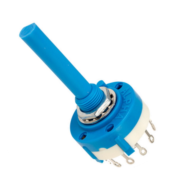
Rotary Break Before Make Switch 2 Pole 6 Way
2 Pole 6 way high quality low current break before make rotary wafer switch with 9.8mm diameter mounting and solder connections to the rear. Each switch has an adjustable stop washer supplied to re...
www.railwayscenics.com
or
Make Before Break Rotary Switch 4 Pole 3 Way
4 Pole 3 way high quality low current make before break rotary wafer switch with 9.8mm diameter mounting and solder connections to the rear. Each switch has an adjustable stop washer supplied to re...
www.railwayscenics.com
inevitably they do not show a photo of the back, which would help but they do have an excellent diagram
Electrical switch types used in model railways | Railwayscenics
Railwayscenics help guide to the different types of electrical switches used in model railways and other hobby areas
www.railwayscenics.com
try your wiring like this;

)") ) is wired up to one pole, then if another colour, say green, is at 180 degrees to it in the opposite pole, then they light up together. And if the Yellow is wired to one side, but the position 180 degrees to it in the opposite pole is vacant, then only the yellow will light up.
) is wired up to one pole, then if another colour, say green, is at 180 degrees to it in the opposite pole, then they light up together. And if the Yellow is wired to one side, but the position 180 degrees to it in the opposite pole is vacant, then only the yellow will light up.
 ).
). ), but I’m willing to give it a couple more days worth of frustration and am beginning to enjoy the electrical challenge thanks to Simon’s generous contribution.
")


