You are using an out of date browser. It may not display this or other websites correctly.
You should upgrade or use an alternative browser.
You should upgrade or use an alternative browser.
TFW’s workshop
- Thread starter Tim Watson
- Start date
Tim Watson
Western Thunderer
Richard Wilson and I spent a productive day trying out the alignment of the York Road plan against the relevant baseboard and station building. This has been almost completely re-made internally towards the back to ensure that the lift shafts and lobbies are in exactly the correct position to line up with the plan at platform level.
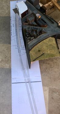
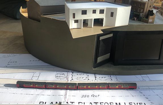
The platform line to Finsbury Park will be hidden under the layout, but the up line and crossover to the north of the station will be fully visible. The plan may not be 100% accurate in that area, but we now have the full prototype plan showing tunnel sizes etc, so that it can be made correctly. It is almost certain that the station building will be removable, as there will be more of the underground structures modelled - the gents loo will therefore be made - it is no wider than the line of the platform track. The ‘area’ in the far left corner won’t be represented. The television screen will probably be covered over, when the underground section is on display.
Richard has mocked up the tube tunnel rings as a 3D print, which will save a vast amount of work and be very robust. The distance between rings is currently 30” - it should be 18-23”, but that will be modified in production. The different diameters for the crossing tunnel civil engineering can also be made as required.
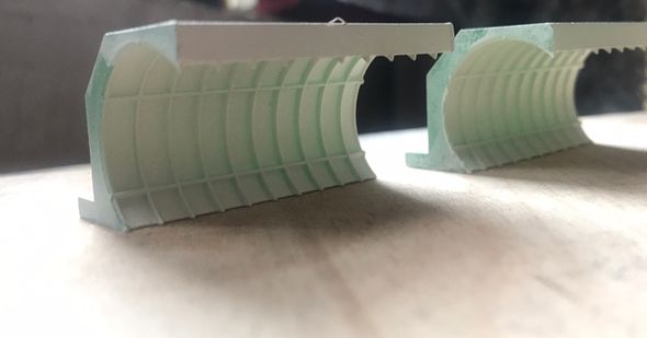
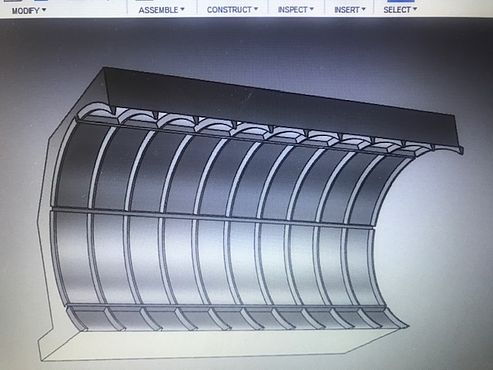
The tunnel bore is generous on size, but that will be important for dynamic tolerances and it could also allow an N gauge tube train to pass, should one ever be manufactured.
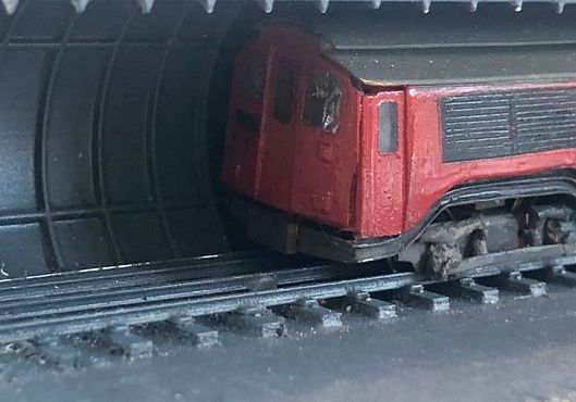
The train in the image is sitting on a piece of fully sleepered track, but the production track will be more nearly flush ballasted and the cement infill in the lower part of the rings will also be included in the 3D print. I think it is fair to say that without the availability of CAD and modern manufacturing techniques, this line would be very much harder to make! It is also quite gratifying to bring all the modern techniques to bear on a 35 year old layout.
Tim


The platform line to Finsbury Park will be hidden under the layout, but the up line and crossover to the north of the station will be fully visible. The plan may not be 100% accurate in that area, but we now have the full prototype plan showing tunnel sizes etc, so that it can be made correctly. It is almost certain that the station building will be removable, as there will be more of the underground structures modelled - the gents loo will therefore be made - it is no wider than the line of the platform track. The ‘area’ in the far left corner won’t be represented. The television screen will probably be covered over, when the underground section is on display.
Richard has mocked up the tube tunnel rings as a 3D print, which will save a vast amount of work and be very robust. The distance between rings is currently 30” - it should be 18-23”, but that will be modified in production. The different diameters for the crossing tunnel civil engineering can also be made as required.


The tunnel bore is generous on size, but that will be important for dynamic tolerances and it could also allow an N gauge tube train to pass, should one ever be manufactured.

The train in the image is sitting on a piece of fully sleepered track, but the production track will be more nearly flush ballasted and the cement infill in the lower part of the rings will also be included in the 3D print. I think it is fair to say that without the availability of CAD and modern manufacturing techniques, this line would be very much harder to make! It is also quite gratifying to bring all the modern techniques to bear on a 35 year old layout.
Tim
Last edited:
Tim Watson
Western Thunderer
Overseer
Western Thunderer
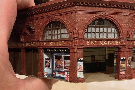
Tim this is looking amazing. I have been meaning to ask about the lettering on the building. You appear to have modelled it as it looks now with the original raised lettering hacked off the faience tiles leaving a rough pale unglazed shape for the letters. I am not sure what year you are portraying but the defaced letters would never have been seen while the station was operating. Early on the raised letters would have been visible, then later with corporate image changes enamel signs were fixed over these areas.
Tim Watson
Western Thunderer
The lettering was never covered over when the station was open. It was cut back for the printer’s signs to be affixed when no longer in use by LT. York Road
I have been thinking about sharpening up the letters a bit, perhaps by adding a little shading to hint at the relief. Trouble is, there is an awful lot of them.
Tim
I have been thinking about sharpening up the letters a bit, perhaps by adding a little shading to hint at the relief. Trouble is, there is an awful lot of them.
Tim
Tim Watson
Western Thunderer
Tim Watson
Western Thunderer
Overseer
Western Thunderer
York Road station is certainly looking like Leslie Green's vision for the tube stations.

The reason I was querying the lettering earlier was because the design was modified for the 1907 built stations (the later ones of the 30 plus stations built 1905 - 1907) to include two white bands to increase the visibility of the stations in the street, as at Hampstead. Far less stylish. Some, but not all, of the earlier stations were modified with the white bands quite early on. I have no information regarding this for York Road.


The reason I was querying the lettering earlier was because the design was modified for the 1907 built stations (the later ones of the 30 plus stations built 1905 - 1907) to include two white bands to increase the visibility of the stations in the street, as at Hampstead. Far less stylish. Some, but not all, of the earlier stations were modified with the white bands quite early on. I have no information regarding this for York Road.

Tim Watson
Western Thunderer
Thanks Overseer. I wasn’t content with the original lettering and highlights have made it look 3D and reflective, which is what it was.
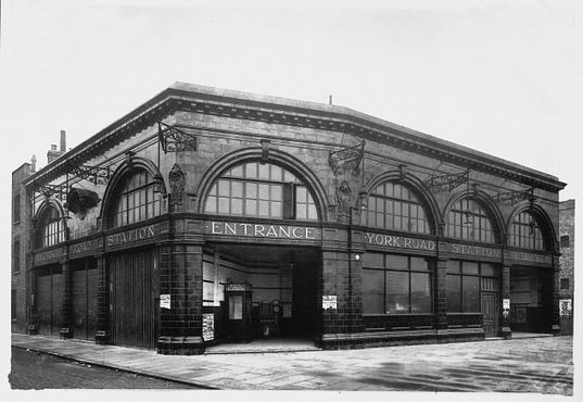
The clean lines were soon lost, with a smattering of posters and a vertical illuminated version of the UndergrounD sign, as well as a reduction in the number of outside lights.
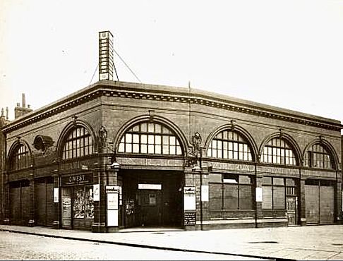 (Unfortunately, I don’t yet have a high res version of this image.) The model has neither of these fittings, as yet, but etches and artwork are already prepared. They will be very vulnerable to handling so won’t be installed yet, especially as the ground floor interior at the back is being made visible. It will feature the gents and ladies toilet, but also including some of the below ground sections such as the lift and stair shafts. These may have cutaways to show their contents.
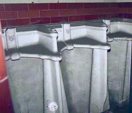
CAD artwork has been drawn up for these in Australia and the sanitary ware will be 3D printed.
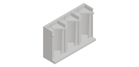
A simple station building has turned into a major project, but it will add a huge amount of interest and be quite educational - I hope.
Tim

The clean lines were soon lost, with a smattering of posters and a vertical illuminated version of the UndergrounD sign, as well as a reduction in the number of outside lights.
 (Unfortunately, I don’t yet have a high res version of this image.) The model has neither of these fittings, as yet, but etches and artwork are already prepared. They will be very vulnerable to handling so won’t be installed yet, especially as the ground floor interior at the back is being made visible. It will feature the gents and ladies toilet, but also including some of the below ground sections such as the lift and stair shafts. These may have cutaways to show their contents.
CAD artwork has been drawn up for these in Australia and the sanitary ware will be 3D printed.

A simple station building has turned into a major project, but it will add a huge amount of interest and be quite educational - I hope.
Tim
Yorkshire Dave
Western Thunderer
The reason I was querying the lettering earlier was because the design was modified for the 1907 built stations (the later ones of the 30 plus stations built 1905 - 1907) to include two white bands to increase the visibility of the stations in the street, as at Hampstead. Far less stylish. Some, but not all, of the earlier stations were modified with the white bands quite early on. I have no information regarding this for York Road.
Interesting - this is something I've never paid attention to. I also see the lettering has become less ornate.
It could be the white bands were introduced for the Hampstead Tube to differentiate it from the other Yerkes (UNDERGROUND group) tube lines.
I'll dig around in my LT books to see if I can turn anything up.
A simple station building has turned into a major project, but it will add a huge amount of interest and be quite educational - I hope.
The whole thread is interesting as I have an interest in LT and it's predecessors (mainly Met).
It is also enlightening from the point of view the LT central area underground lines is a system we all have used to get from A to B perhaps without any thought as to what lies behind it due the hidden nature. Unlike the visible surface sections and the surface lines.
Tim Watson
Western Thunderer
There was a roof vent for the air ducting on the back corner of the station building. I have always made these solid out of white and black styrene sheet, cut into the components as seen in this image:
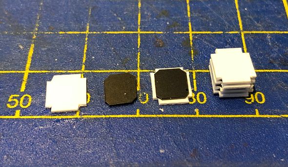
These are stacked together and the recessed corners tidied up with a file, once solid. The top edges of the white bits are chamfered so as to look like the angled slats. Square styrene posts are fixed to each corner.
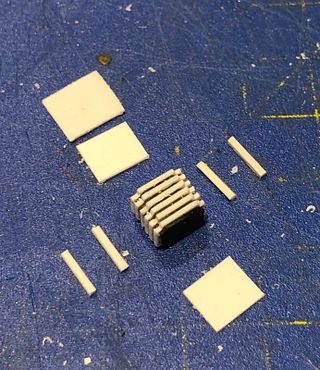
After a bit of final fettling with a file the end product is quite sturdy.
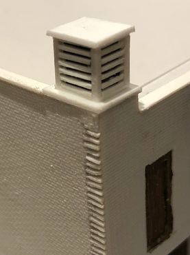
The use of black styrene is not essential, but it does make painting easier. No one has yet complained that they can’t see through the slats - shouldn’t have said that should I? It just needs the rest of the ducting and the fan made now...
Tim
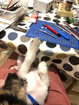
P.S. Modelling can be soooo relaxing.

These are stacked together and the recessed corners tidied up with a file, once solid. The top edges of the white bits are chamfered so as to look like the angled slats. Square styrene posts are fixed to each corner.

After a bit of final fettling with a file the end product is quite sturdy.

The use of black styrene is not essential, but it does make painting easier. No one has yet complained that they can’t see through the slats - shouldn’t have said that should I? It just needs the rest of the ducting and the fan made now...
Tim
P.S. Modelling can be soooo relaxing.

Tim Watson
Western Thunderer
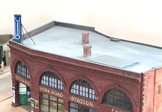
By 1927, York Road tube station was well covered in posters and corporate signage.

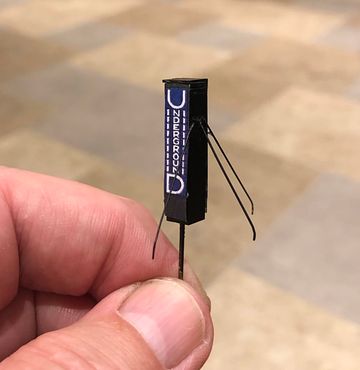
The upright UndergrounD sign is unusual (to me at any rate) and had to be modelled. It was milled from a lump of brass and two 0.3mm and one 0.4mm diameter holes drilled at the back for the props, which were soldered into place. For added security, there is a 0.9mm brass dowel locating it through the main structure.
The artwork for the upright signs was drawn up four times oversize and reduced to 2mm scale when printed: in that way draughting errors become less conspicuous. It’s all a bit black at the moment, but some weathering will improve it.
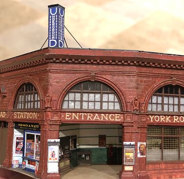
If it wasn’t already obvious, there is now no doubt that this is a tube station. Time to get some paint on the roof and some of the walls now.
Tim

The upright UndergrounD sign is unusual (to me at any rate) and had to be modelled. It was milled from a lump of brass and two 0.3mm and one 0.4mm diameter holes drilled at the back for the props, which were soldered into place. For added security, there is a 0.9mm brass dowel locating it through the main structure.

The artwork for the upright signs was drawn up four times oversize and reduced to 2mm scale when printed: in that way draughting errors become less conspicuous. It’s all a bit black at the moment, but some weathering will improve it.

If it wasn’t already obvious, there is now no doubt that this is a tube station. Time to get some paint on the roof and some of the walls now.
Tim
Last edited:
Tim Watson
Western Thunderer
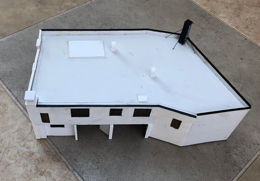
Had a first go at the roof this evening. I have fitted two chimney stacks where I think they might go and fitted a black strip to the top of the parapet copings. This prevents the white styrene showing through if a building is going to get handled a bit.
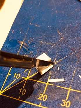
The stacks were made from solid Evergreen strip, clad in our brick styrene as shown: this building technique does not require great accuracy in measuring.
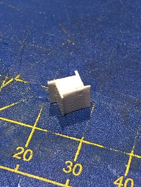
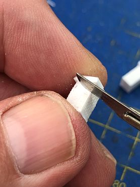
The excess vertical strips were cut off with a scalpel, followed by dressing the corners with a file.
The bottom of the stack was given a 1mm thick styrene layer to represent the flashing and the top decorative courses also built out with layers. The edges of the brickwork were notched with the scalpel blade to soften them. Plastikard buildings often look too ‘sharp’ and ‘edgy’. For a more poorly maintained building a slotting file will give a more pronounced mortar course. The chimney castings complete with flaunchings will be epoxied on at a later stage.
The roof was initially given a light grey wash applied in a random direction, then a darker grey with the brush in one direction only, followed by the light colour again at 90 degrees, building up texture and depth of colour along the way. Finally, a wash of a brown-grey was run along the gutters, corners and crevices. When the paint has hardened overnight, I will paint in some dried up puddles and other features and add some further weathering using powders, especially around the vent.
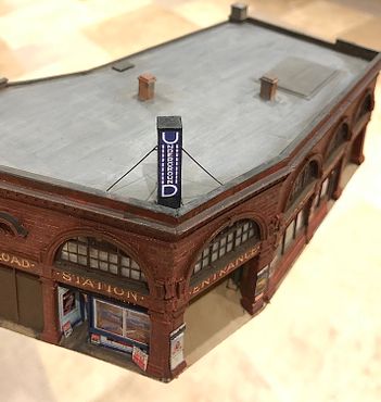
The building is looking very solid sitting on the layout - I believe a worthwhile improvement on the original concept (I’ll take some comparison photos soon).
Tim

The stacks were made from solid Evergreen strip, clad in our brick styrene as shown: this building technique does not require great accuracy in measuring.

The excess vertical strips were cut off with a scalpel, followed by dressing the corners with a file.

The bottom of the stack was given a 1mm thick styrene layer to represent the flashing and the top decorative courses also built out with layers. The edges of the brickwork were notched with the scalpel blade to soften them. Plastikard buildings often look too ‘sharp’ and ‘edgy’. For a more poorly maintained building a slotting file will give a more pronounced mortar course. The chimney castings complete with flaunchings will be epoxied on at a later stage.

The roof was initially given a light grey wash applied in a random direction, then a darker grey with the brush in one direction only, followed by the light colour again at 90 degrees, building up texture and depth of colour along the way. Finally, a wash of a brown-grey was run along the gutters, corners and crevices. When the paint has hardened overnight, I will paint in some dried up puddles and other features and add some further weathering using powders, especially around the vent.

The building is looking very solid sitting on the layout - I believe a worthwhile improvement on the original concept (I’ll take some comparison photos soon).
Tim
Last edited:
Tim Watson
Western Thunderer
As promised, some comparisons between the semi-skimmed and full fat versions of the tube station.
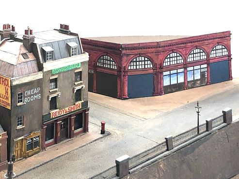
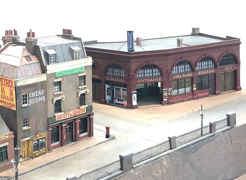
This is the operator’s view.
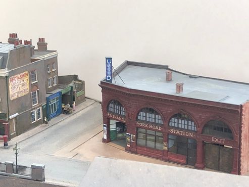
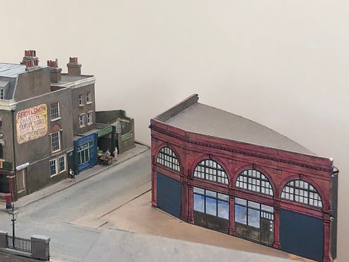
And this is a view the public will get.
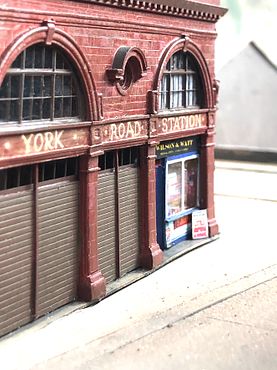
The dried up algae containing puddles have been added to the roof. A bit of green always makes a model come to life.
The pavement area will probably be made from 0.6mm steel plate and attached to the building: this will protect the fine details such as the lamps (yet to be fitted) and allow the paving to be held down with buried magnets for the removable building.
Tim


This is the operator’s view.


And this is a view the public will get.

The dried up algae containing puddles have been added to the roof. A bit of green always makes a model come to life.

The pavement area will probably be made from 0.6mm steel plate and attached to the building: this will protect the fine details such as the lamps (yet to be fitted) and allow the paving to be held down with buried magnets for the removable building.
Tim
Last edited:
Yorkshire Dave
Western Thunderer
Excellent, well worth it. It's not often you see Leslie Green buildings. And modelling the entire building is better from the operator's viewpoint.
Tim Watson
Western Thunderer
We have been doing quite a lot of planning and plotting for the York Road tube station site and its alignment over the last week, having tried the board and station out at Keen House with the southern end of Belle Isle in place. Not a huge amount to show for these efforts but at least the steel baseplate is now the correct shape.
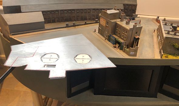
The paper plan can be seen under the steel, showing the lift shafts and cars (only the left hand, southern, one was ever used) and the stairs down to the basement. To the left of the steel plate the layout will be expanded slightly to square off the York Road and we will merge Bingley and Randells Road at the front on the right. There is room to accommodate this in the storage box.
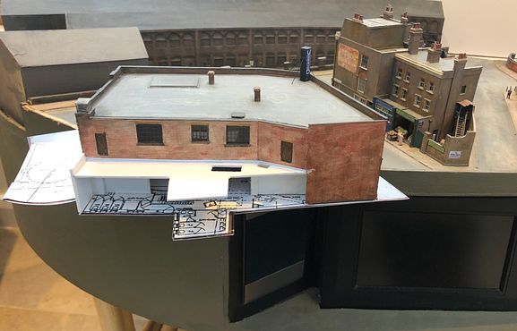
The magnets for holding the steel down are ordinary ferrous type at present but these will be replaced with modern materials with a stronger flux very shortly. The station building and platforms are a bit further out than originally intended, but this allows us to make the lift shaft operational. The shafts will be made from 51mm brass tube. I now have drawings for parts of the lift mechanism.
We’re away in the van this weekend so I expect I’ll make a start on some of the rear interior detail, such as the staff room and basement stairs.
Tim

The paper plan can be seen under the steel, showing the lift shafts and cars (only the left hand, southern, one was ever used) and the stairs down to the basement. To the left of the steel plate the layout will be expanded slightly to square off the York Road and we will merge Bingley and Randells Road at the front on the right. There is room to accommodate this in the storage box.

The magnets for holding the steel down are ordinary ferrous type at present but these will be replaced with modern materials with a stronger flux very shortly. The station building and platforms are a bit further out than originally intended, but this allows us to make the lift shaft operational. The shafts will be made from 51mm brass tube. I now have drawings for parts of the lift mechanism.
We’re away in the van this weekend so I expect I’ll make a start on some of the rear interior detail, such as the staff room and basement stairs.
Tim
Last edited:
Tim Watson
Western Thunderer
I finally reached quite a momentous stage in the construction of the tube station today when it was finally assembled on the steel plate. The rare earth magnets to hold the plate are simply placed in holes in the plywood sun-base and locked in with super glue.
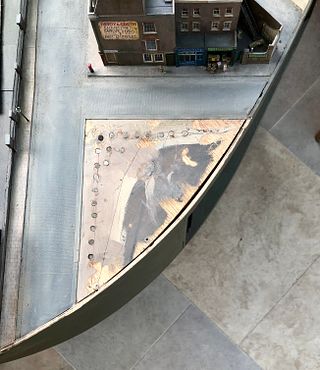
The strong flux from these little magnets really holds down the steel plate extremely well. This was chemically blackened so that it won’t show any shiny edges. The weird tongue-like shape at the southern end of the building is the roof of the basement passageway that meets up with the spiral escape stair shaft.
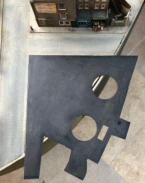
As mentioned previously, the roads adjoining the building plot will be extended to put it into better context.
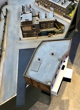
As I have also alluded, more and more information has appeared as this project has progressed. I now have drawings of the lifts and so the image below was taken from them, scaled to size and used to improve the accuracy of the visible lift lobby.
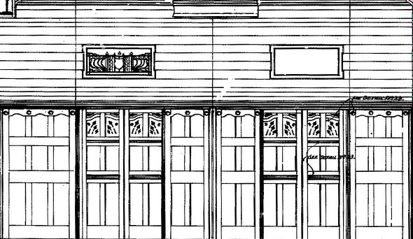
These were painted and fitted over the weekend. It will be good to now be able to get on with some proper modelling rather than civil engineering.
Tim

The strong flux from these little magnets really holds down the steel plate extremely well. This was chemically blackened so that it won’t show any shiny edges. The weird tongue-like shape at the southern end of the building is the roof of the basement passageway that meets up with the spiral escape stair shaft.

As mentioned previously, the roads adjoining the building plot will be extended to put it into better context.

As I have also alluded, more and more information has appeared as this project has progressed. I now have drawings of the lifts and so the image below was taken from them, scaled to size and used to improve the accuracy of the visible lift lobby.

These were painted and fitted over the weekend. It will be good to now be able to get on with some proper modelling rather than civil engineering.
Tim
john lewsey
Western Thunderer
Beautiful work Tim
Tim Watson
Western Thunderer
The ground floor and basement of York Road tube is going to be a it like a dolls house at the back, visible to the public from the layout front. The ladies toilets will be on the left (brown and red tiles) and the gents in the bit that sticks out. There will be Perspex walls along the front face. We should be getting a delivery of porcelain fittings fairly soon.
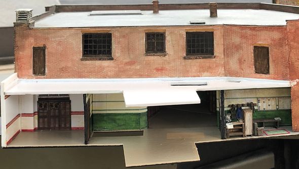
We can now have a peak into the staff mess room.
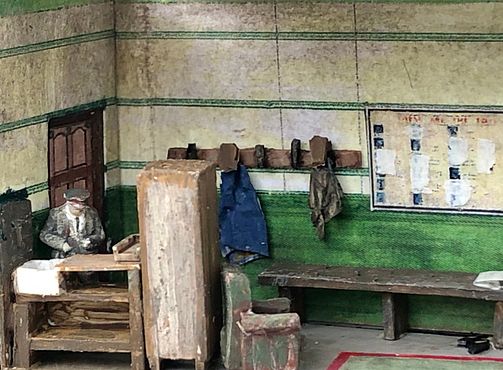
The armchair has definitely seen better days.
Richard Wilson has now made the definitive visible track plan. The sector plate arrangement at the south end would not be used when YR is attached to CF as there would not be room; up trains will reverse direction at YR and the baseboard will stop at the platform end. The crossing will be modelled exactly to scale, with the cut away tunnel bores correctly portrayed (we have copies of the original drawings). Only the front line will be visible. The curvaceous purple line is the CF baseboard edge.

Tim

We can now have a peak into the staff mess room.

The armchair has definitely seen better days.
Richard Wilson has now made the definitive visible track plan. The sector plate arrangement at the south end would not be used when YR is attached to CF as there would not be room; up trains will reverse direction at YR and the baseboard will stop at the platform end. The crossing will be modelled exactly to scale, with the cut away tunnel bores correctly portrayed (we have copies of the original drawings). Only the front line will be visible. The curvaceous purple line is the CF baseboard edge.

Tim
Tim Watson
Western Thunderer
I have started to make good progress on the basement and stairs to the spiral escape stairs on YR. the only part that is really visible is a store room, but it will get interesting in the vicinity of my left hand where there is a further sub basement, top of the spiral stairs and a ventilation plant room. This will be modelled and visible as a cutaway. The ducting is in place, but not visible in this view, being tucked under the corner of the main building.
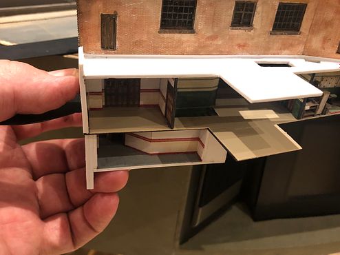
The escape passage can be seen when the components are separated, following the outline of the lift shaft at one point. I will probably use magnets to locate these components, at least during the early stages of construction.
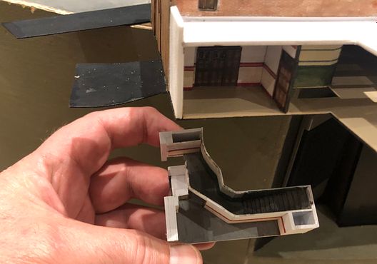
it doesn’t look like a great deal of work, but it takes quite a while to work out how everything fits together. Seeing inside the workings of a tube station is not an everyday occurrence for me...
Tim

The escape passage can be seen when the components are separated, following the outline of the lift shaft at one point. I will probably use magnets to locate these components, at least during the early stages of construction.

it doesn’t look like a great deal of work, but it takes quite a while to work out how everything fits together. Seeing inside the workings of a tube station is not an everyday occurrence for me...
Tim

