Monks Ferry: a layout for the Grandchildren.

jonte

Western Thunderer
"I was going to forego a turntable, the need for which was somewhat obviated by the option of a reverse loop..."

Quite the opposite! If you have a return loop (and enjoy the wiring challenges that it may pose) you will have locos that need to be turned! They can, of course, be sent off to the return loop again, but where's the fun in that?

atb
Simon
Thanks for the benefit of your obs, Simon, but I’ve traced (on my poor sketch of the plan :() the path of a loco facing the terminus buffers, that backs out onto the mainline, runs round the ‘loop’, and finally back into the terminus facing forwards (in order to depart at the head of a train) again:

IMG_2490.jpeg

Here’s the gizmo to operate the loop:

IMG_2494.jpeg

Cheers,

Jon
 

jonte

Western Thunderer
The weather abated about two-ish, so it was out with one of my latest gadgets, and the 8’x2’ 6mm plywood sheets intended for the track base, which I frustratingly managed to cut into lengths of 8’ x 45mm strips:

a66c624d-864a-4a8c-aaa9-6227fc90206b.jpegcc85980f-a005-49f1-bb63-052ece00ad8a.jpeg1981d205-4180-46fd-a5ce-d1ed048aba50.jpeg

…….and a couple of hours later, I had about two hundred or so feet of the stuff which should be enough for the Norman beams (seen here with several metres of 45 x 35(?)mm PAR, which will cut into blocks for inside the beams:

d64c7a99-1959-4a72-bea3-ed716fbbc0d9.jpeg

At least another job out of the way.

jonte
 

jonte

Western Thunderer
The turntable of which I made mention arrived in yesterday’s post, so this morning I gave it a go:


I’m very pleased with it, as despite being second hand, it lines up beautifully.

A bonus: on opening, enclosed was a pamphlet from the East Lancs Preserved Railway, stating that the proceeds from the sale will go to restoring a tank engine, which makes my purchase all the more worthwhile. Consequently, I’ve saved the seller’s details as they will be my first port of call in future.

Now back to cutting wood.

jonte
 

timbowales

Western Thunderer
The turntable of which I made mention arrived in yesterday’s post, so this morning I gave it a go:


I’m very pleased with it, as despite being second hand, it lines up beautifully.

A bonus: on opening, enclosed was a pamphlet from the East Lancs Preserved Railway, stating that the proceeds from the sale will go to restoring a tank engine, which makes my purchase all the more worthwhile. Consequently, I’ve saved the seller’s details as they will be my first port of call in future.

Now back to cutting wood.

jonte
I like the idea of supporting restorations that way.
Can you share the sellers details please?
 

jonte

Western Thunderer
The priority was to fabricate two sets of beams which would serve to join the two outermost boards to the centre one, ensuring that they were level and accurate enough for fitting the required male and female carpenters dowels, which it is essential to fit at this early juncture .
Once achieved, the rest of the (three) frames could be built.

So in time honoured fashion, blocks of the required sizes were cut for the central part of the Barry Norman style beams, together with a collection of henge-like stanchions (I lost count in number in the late forties or so) on which the track bed would be carried. These were glued and screwed between the outside strips, shown earlier on the thread.

Now, I’ve read that the Norman beams are prone to warping, and mine were no exception:

IMG_0447.jpeg

That said, the screws still proud of the wood surface as in the previous shot, didn’t help, and after letting the whole dry for twenty four hours or probably more (it really is a piecemeal approach these days), the screws were countersunk, which for some reason slightly improved matters:

IMG_0448.jpegIMG_0449.jpeg

So, attention tenuously turned to fitting the dowels and bolts to hold the boards together.

Ensuring the assembly was as flat as possible on the bench, they were firmly clamped together:

IMG_0450.jpeg

Long screws purchased for the task were then used to screw then together so that the clamps could be removed for ease of drilling (screwing everything together is so long winded as I’ve yet to purchase a decent impact driver for the purpose, and despite the odd hint or two, my brother in law was reluctant to loan me his de Walt version….). Anyway, with the clamps removed, I reached for my drills…….only to realise thy weren’t long enough. So a day was spent hunting round for a specialist to supply a 7,5mm long drill, as the usual retailers only stock discrete sizes (B&Q alleged they did, until they cancelled my click n collect realising they didn’t) - I also picked up one of these:

539F4E8F-5183-4F8A-BDB0-2785003C3333.jpeg

….a 10mm brute for a tenner, to drill the holes to receive the M10 bolts, but what a palava trying to get it to drill through without a struggle. On the second hole, I managed to rip the back out of the rear ply strip after the scrap block placed beneath for the purpose, slipped during the wrestling match that ensued……….

So it was back out to Toolstation to pick up a spade drill for a reasonable fee, although it still didn’t prove an easy job, but better than the last.

Anyway, I managed to address one set of beams, although, for some reason, the holes for one set of dowels was oversize - same drill used and pilot hole - so I’ll drill another next time I’m at the bench:

IMG_2515.jpeg

Shown together with M10 bolts attached (appropriate washers were purchased in addition, and a set of wing nuts which are out of sight in the next shot):

IMG_2516.jpeg

I’m also going to fit another bolt just as belt n braces.

Incidentally, the boards will also be linked by split hinges fixed to either side of the joint externally.

Now, it’s on to the second set.

Cheers,

jonte
 

jonte

Western Thunderer
I submit this post, not by way of some new and exciting development unfortunately, but to report that earlier today - after sitting pondering somewhat - an uncomfortable thought occurred. I rushed outside to confirm my suspicions and was proved right: after all the effort I’d gone to secure a long 7.5 milli bit, I realised that in my haste I’d picked up the wrong bit from the pool of bits littering the bench. I was in fact using an 8 milli bit………hence the sloppy fits of the dowels on the first set shown in my last post!

Anyway, in fits and starts during the day, I addressed the second set of beams, although this time with correct bit.

Here are some pictures of the finished article, including one or two of how the dowels should look:

IMG_0457.jpegIMG_0458.jpegIMG_0460.jpegIMG_0461.jpeg

At my next visit to the bench, whenever that may be as grand parenting duties will take up the rest of this week, I’ll rectify the dowels on the first set.

Still, I’m pleased that the beams are now straight and the stanchions are level.

In the meantime, I need to pick up some more washers and wing nuts.

Cheers for now.

jonte
 

Attachments

  • IMG_0459.jpeg
    IMG_0459.jpeg
    52.3 KB · Views: 1

jonte

Western Thunderer
Been a bit of a quandary of late about how next to proceed, and I admit there’s been more thinking than doing.
That said, only the earliest part of the week is available for projects these days, so the pondering didn’t interfere too much with the doing. And of course, the limited space in my workshop and model room, especially with boards of this size, has only exacerbated matters, especially when it came to the next stage of making the side beams.

To cut a long story short, I decided that the primary task at this juncture was to ensure a fixed distance between the end beams of this centre section (as at is from this section that the outer boards will be constructed) as shown previously. After much faffing (or is it phaphing?) I decided that the best bet was to screw the beams to the ply track base which would be at the distance required. This was performed by screwing each corner from underneath, a bit of a dance which involved turning the structure (with great difficulty in the restricted space of the model room: the workshop was even tighter!) in a circular fashion (as did necessitate the rest of the construction, to say nothing of the clambering on and over the work bench, at one stage having got myself stranded, having to ring my wife to come out and help me down……when did I get this old exactly?).

Anyway, my aim was achieved, so it was out with the mire saw to cut the necessary lengths of strip and blocks required, my intention being to build the side beams with the end beams fixed to the base as described. Problem was however (isn’t there ruddy well always?) the ply track base was warped (like all the other darned wood I seem to acquire these days), so that idea was put on the back burner, as a flat bench to work from is essential. I reckoned that do so would require a bigger area and bench, one that allowed me unrestricted access to both sides for drilling/gluing/screwing and old uncle tom cobbley n all. Dream on.

So I thought, ‘rowlocks!’ and considered I might as well make the most of my time by unscrewing the beams and reattaching the ply track base above where it should go. But how to maintain the distance between the beams? In the end, I cut up some of the PAR intended for the blocks and screwed them each side. In this way, the board could be removed (in a circular fashion as before, whilst praying that the whole ensemble wouldn’t twist or worse… I really hate this hobby at times….), while keeping the beams at the required distance apart. Incidentally, a thought crossed my mind before doing so: drill the beams with the ply base attached before unscrewing so that, theoretically, the base can be reattached to the top using these holes for the screws. A 200mm long drill was duly ordered for fast the task, and arrived pronto via the online retailer bearing the same name as the jungle. It proved a bum decision, as most of my ideas are: drills of this fine-ness (is that even a word, Dave?) tend to bow when drilling through five inches of knotted wood, despite the use of a drill guide. So that was that. Luckily, I’d had the presence of mind to mark the beams and ply base appropriately, which made the fitting only slightly easier, by simply drilling and screwing from above, which I carried out earlier this morning before collecting my granddaughter from nursery.

A morning’s work was more than enough on this project anyway.

Enough waffle; some piccies:

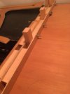
Loosely placed for lining up witness marks to ensure correct fit:

IMG_0465.jpegIMG_0467.jpeg

In the following shot, you can see how the beams warp when not bolted together, thus initially, only the outside uprights were fixed, the inners being so only after the beams were fixed together with bolts to ‘pull’ them outwards (I still need to go shopping for more washers and wing nuts):

Side beamIMG_0468.jpeg appar


IMG_0467.jpeg

My knees just in (lower) shot as evidence of my poor mountaineering skills:

IMG_0466.jpeg


IMG_0467.jpeg


IMG_0468.jpegIMG_0469.jpegIMG_0470.jpegIMG_0471.jpeg

I shaln’t ‘narrate’ the above any further as am experiencing difficulties uploading and adding text. Apologies for the jumbled appearance.

At the next visit, it will be back to addressing the side beams. The only solution to making the task easier, is to fabricate an external bench, one from a section of loft flooring (chipboard) - back to the timber merchant - the only source of ‘flat wood’ I know of currently, which will form the bench top of required size, stretched across two wooden workhorses, and the whole ensemble assembled beneath a mini marquee for shelter, as it never seems to cease raining these days…….

Will we ever get to play trains…….

Till next time.

jonte

Edit: the beams will be glued, and screws countersunk once the boards are completed.
 

jonte

Western Thunderer
Managed an hour or two over a busy weekend to address the ‘side beams’ subject of my last.

Reluctantly, I binned the idea of Norman style beams here, as their tendency to warp concerned me. Thus, for added strength and security (the internal cross members will be attached to these so I need them as true as possible), I decided to opt for the good old fashioned approach of using a length of PAR, but ‘clothed’ in ply strips to match the rest.

In an attempt to ensure that the table surface was as flat as possible upon which to attach the side beams , and for ease of access, I went outside once more - thankfully it didn’t rain, for once - and constructed a makeshift bench from odds and ends of ply, resting on carpenters horses, with some chipboard flooring placed on top, purchased for the purpose.

It didn’t work as well as expected, so for the next attempt, I took the unit back into my modelling room and attached the straightest/flattest piece of timber to the base of the board with clamps, and constructed the beam upon it. With the beam attached, I then fixed the outside ply strip, glued n screwed as before. The only problem with this method was access to doing the same for the rear strip. In the end, I glued the sections together and held them in place with clamps to dry. In order to prevent the whole lot becoming one, wrapping the makeshift bench in the form of a plank in cling film.

Here are some pictures:

Not enough clamps, so masking tape pressed into service:

IMG_0473.jpeg


The finished beam (I’ll sand the bottom smooth next time):

IMG_0474.jpeg


An underside shot to show the screws present on the rear beam, the first method as discussed affording me access, not possible with the later option:

IMG_0476.jpeg

(They’re not as visible as I thought….).

I’ll return to Norman beams with the internals (not an issue with the side beams as they’re not employed to support the raised track bed), as the gap in between the strips helps to hold the uprights in place whilst fixing, and which will supplement those at the ends. I’ll probably opt for longitudinal beams to shore up the transverse sections, which in some ways defeats the object of the exercise in terms of weight saving, but in this case - as it’s not an exhibition layout, for which the method was designed - strength is more important than weight saving.

So that’s the next job, which will have to wait for now as we’re taking a short break.

Cheers for now, and thanks for your interest and likes.

jonte
 
Top