jonte
Western Thunderer
With some distractions sorted, including the much dreaded purge of my modelling den and rearrangement of the newly completed workshop which occupies the inner half of my garage, thoughts could now return to some modelling, and the long awaited commencement of the grandchildren’s train set (guess this makes me a fully paid up member of the ‘trainset-brigade’, hey Dave? ).
).
With plans created, recreated and binned aplenty, I eventually went back to the beginning and to a plan shown earlier in the thread. You see, folks, I came to the conclusion that a train set without a terminus station and return loop as per Dublo of old, well, wasn’t a train set in my book, so here we are…..back to the beginning (but with one or two amendments- aren’t there always ? ):
):
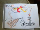
Treating the above more as a guide than a plan, I went back to our roots in the hobby, and simply selected a pick n mix of points (Hornby) which I assembled into something resembling a station throat/junction from the main line:
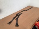
This would satisfy my first thoughts, which were of intercity services arriving and departing from designated platforms i.e. ‘depart one side of station’, ‘arrive at another’, each and every time. But then the thought occurred to me, ‘what if I wanted to perform each service from ‘any’ vacant platform?. So, with the purchase of an additional diamond crossing, I came up with this:
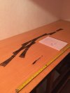
With the crossover to the right, trains could now enter any platform from either upside/downside track (can never work out which is which, sorry). And so, with the addition of a second set of crossovers and the movement of the entry to the loop from one side to the other, this is what I arrived at:
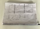
The point shown lower left of the ‘plan’ will lead to an MPD and perhaps some goods facilities (TBA).
The numbers 1, 2 and 3 shown, relate to individual baseboards, which will join together via carpenters’ dowels to form a layout measuring a total area of around 12.5’ x 4’, which makes the maximum use of space, whilst still allowing for access and a spot of storage.
The main reason for deciding on individual boards, was to facilitate its eventual removal for whatever reason (the tight angle to the door makes anything much over five feet in length nigh on impossible!).
So, with a plan decided, a couple of trips to the timber yard were in order. Initially, I purchased 6mm ply for the track bed, but as can be seen from the following photo, the stuff just wasn’t up to the job….
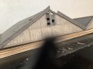
…..so, it was back, to reorder something more robust, of 12mm variety.
Not trusting the wood yard to cut the timber as required, I simply ordered two sheets of the stuff, and began cutting them to size via the use of a cheap plunge saw purchased for the task, which surprisingly worked quite well. Rather than buy a further board for the final baseboard, I just glued a leftover section to make up the shortfall, as the two sheets plus some 2”x1.5” timber (more about later) in total, came to just over a hundred quid delivered. COVID real did re-set the market price of everything it seems!:
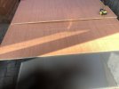
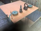
Finally, the three boards in place in my den, the joint as described just being visible nearest the camera, which will be sanded smooth:
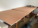
I was going to place the station at this end…..:
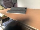
…….. however, in this position, it will make it difficult for the observer to see the trains running into the platforms, so will switch it round to the position shown in the previous picture. This will also have the complex arrangement of the junction nearest the observer (btw: only the central part of the roof will be used, so some deft removal of the outer sections will be required, which I’m dreading!).
The next stage will be to lay the trackwork onto the boards, so they can be marked out for cutting with a jig saw (thankfully, I already have one of these !). Then it will be onto making the frames upon which the trackbed will sit.
To this end, I’ve opted for the Barry Norman method of baseboard building, with which I’ve no doubt most will be familiar, so will refrain from repeating, apart from to say that I’ll be using the dodgey 6mm ply shown earlier for the beams, strengthened with blocks of the 2”x1.5” PAR timber also mentioned.
Cutting and marking the trackbed for point tie bar locations as mentioned, will help determine the location of each beam, together with relevant size and location of each supporting block. Plus, as this is to be elevated like many of the City of London lines I’ve used as an influence for the setting, the raised blocks onto which the trackbed will rest will be set into gaps in the aforementioned beams. Of course, and as a bonus I feel, this style of baseboard building lends itself to allowing the land to rise and fall at various points, which will be a welcome deviation from the generally accepted ‘trainset on flat baseboard’ style of traditional trainsets.
As many blocks will be required, I outlayed for yet another vital item of equipment, namely a mitre saw, as the wood yard declined to cut around ninety blocks which I reckon will be required by the end, so this build is beginning to get a little expensive, although I’m sure it will come in handy at some point in the future.
Yet another new piece of equipment was purchased, this time in the form of a pillar drill, to ensure vertical holes for the dowels in facing beams (I’m lousy with a drill ). However, before it landed, I realised I’d goofed: it was fine for drilling one ‘Norman’ beam, however, I’d forgotten that the method requires two to be clamped and drilled at the same time………so back it went. I’m afraid the larger drills for the purpose were simply out of my price range.
In the end, I opted for a drill guide from Amazon for less than fifteen quid with delivery. The only problem here is that it only has discrete sizes (no half sizes) such that the 8mm dowels should be a friction fit into a 7.5mm pilot hole, so if it’s too loose a fit, I’ll glue ‘em in with some two-part stuff …..carefully.
So, there we are; at long last.
Cheers for now.
jonte
 ).
).With plans created, recreated and binned aplenty, I eventually went back to the beginning and to a plan shown earlier in the thread. You see, folks, I came to the conclusion that a train set without a terminus station and return loop as per Dublo of old, well, wasn’t a train set in my book, so here we are…..back to the beginning (but with one or two amendments- aren’t there always ?
 ):
):
Treating the above more as a guide than a plan, I went back to our roots in the hobby, and simply selected a pick n mix of points (Hornby) which I assembled into something resembling a station throat/junction from the main line:

This would satisfy my first thoughts, which were of intercity services arriving and departing from designated platforms i.e. ‘depart one side of station’, ‘arrive at another’, each and every time. But then the thought occurred to me, ‘what if I wanted to perform each service from ‘any’ vacant platform?. So, with the purchase of an additional diamond crossing, I came up with this:

With the crossover to the right, trains could now enter any platform from either upside/downside track (can never work out which is which, sorry). And so, with the addition of a second set of crossovers and the movement of the entry to the loop from one side to the other, this is what I arrived at:

The point shown lower left of the ‘plan’ will lead to an MPD and perhaps some goods facilities (TBA).
The numbers 1, 2 and 3 shown, relate to individual baseboards, which will join together via carpenters’ dowels to form a layout measuring a total area of around 12.5’ x 4’, which makes the maximum use of space, whilst still allowing for access and a spot of storage.
The main reason for deciding on individual boards, was to facilitate its eventual removal for whatever reason (the tight angle to the door makes anything much over five feet in length nigh on impossible!).
So, with a plan decided, a couple of trips to the timber yard were in order. Initially, I purchased 6mm ply for the track bed, but as can be seen from the following photo, the stuff just wasn’t up to the job….

…..so, it was back, to reorder something more robust, of 12mm variety.
Not trusting the wood yard to cut the timber as required, I simply ordered two sheets of the stuff, and began cutting them to size via the use of a cheap plunge saw purchased for the task, which surprisingly worked quite well. Rather than buy a further board for the final baseboard, I just glued a leftover section to make up the shortfall, as the two sheets plus some 2”x1.5” timber (more about later) in total, came to just over a hundred quid delivered. COVID real did re-set the market price of everything it seems!:


Finally, the three boards in place in my den, the joint as described just being visible nearest the camera, which will be sanded smooth:

I was going to place the station at this end…..:

…….. however, in this position, it will make it difficult for the observer to see the trains running into the platforms, so will switch it round to the position shown in the previous picture. This will also have the complex arrangement of the junction nearest the observer (btw: only the central part of the roof will be used, so some deft removal of the outer sections will be required, which I’m dreading!).
The next stage will be to lay the trackwork onto the boards, so they can be marked out for cutting with a jig saw (thankfully, I already have one of these !). Then it will be onto making the frames upon which the trackbed will sit.
To this end, I’ve opted for the Barry Norman method of baseboard building, with which I’ve no doubt most will be familiar, so will refrain from repeating, apart from to say that I’ll be using the dodgey 6mm ply shown earlier for the beams, strengthened with blocks of the 2”x1.5” PAR timber also mentioned.
Cutting and marking the trackbed for point tie bar locations as mentioned, will help determine the location of each beam, together with relevant size and location of each supporting block. Plus, as this is to be elevated like many of the City of London lines I’ve used as an influence for the setting, the raised blocks onto which the trackbed will rest will be set into gaps in the aforementioned beams. Of course, and as a bonus I feel, this style of baseboard building lends itself to allowing the land to rise and fall at various points, which will be a welcome deviation from the generally accepted ‘trainset on flat baseboard’ style of traditional trainsets.
As many blocks will be required, I outlayed for yet another vital item of equipment, namely a mitre saw, as the wood yard declined to cut around ninety blocks which I reckon will be required by the end, so this build is beginning to get a little expensive, although I’m sure it will come in handy at some point in the future.
Yet another new piece of equipment was purchased, this time in the form of a pillar drill, to ensure vertical holes for the dowels in facing beams (I’m lousy with a drill
 ). However, before it landed, I realised I’d goofed: it was fine for drilling one ‘Norman’ beam, however, I’d forgotten that the method requires two to be clamped and drilled at the same time………so back it went. I’m afraid the larger drills for the purpose were simply out of my price range.
In the end, I opted for a drill guide from Amazon for less than fifteen quid with delivery. The only problem here is that it only has discrete sizes (no half sizes) such that the 8mm dowels should be a friction fit into a 7.5mm pilot hole, so if it’s too loose a fit, I’ll glue ‘em in with some two-part stuff …..carefully.
So, there we are; at long last.
Cheers for now.
jonte


 !
! , but especially so from one more worldly wise, to say nothing of valuable experience with the real thing, so many thanks for your valued contribution, sir

