Arduinos. And CAN.
when I built PD loco, I had in mind the intent to incorporate it into a larger layout at some indeterminate point in the future, when we get our extension built, so the control panel is on the end of a wander lead. I wanted to include points, turntable and lighting control, along with a socket for the Lenz x-bus, and I also wanted to use a standard 25-way d-plug cable, as nobody wants to make up leads, and they can get damaged with use, so easy replacement is also desirable.
There aren’t enough wires in a 25-way cable! I was advised that using I2C comms between Arduinos was likely to lead to problems, but it worked when I first installed it, and it still works now, but not reliably, and that’s a PITA, so over the last few weeks, I started to rebuild things, to use CAN comms. The MCP2515 modules are cheap and after a few issues, I have them communicating happily, so now I’m reprogramming.
Inevitably, the Arduino pins that are required to communicate with the CAN modules were already used, so that required some rewiring too. This would not have been the case had I started with CAN of course.
The control box is functional, though not pretty, it’ll be much improved by a laminate front panel with trackplan, and a more attractive set of buttons for the turntable. The other switches are lights and program track.
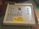
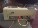
the red button is a reset for the Arduino mega within, the red & black 4mm sockets are track DCC to facilitate use of the test track & rolling road, and the DIN socket allows a Lenz/Roco controller to plug in. The knob is the brightness control for the layout lighting, of which there are 5 channels. The orange and white wires are the temporary CAN connection.
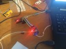
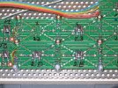
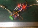
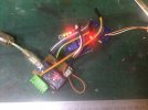
This is a typical slave - the CAN interface is the nearer board, and it’s connected to the Arduino Nano which will eventually be reconnected to the turntable stepper motor. Similar arrangements are connected to the points controller and lighting dimmers.
the CAN interfaces were about 3 quid each, the Arduinos similar money, so it’s within the bounds of realistic money to put a CAN interface and an Arduino pretty much anywhere on a layout (eg in a building, just to have individual lighting control, though you could program a few other features/gimmicks/whatever as well)
it’s all spread across the bench, a table and my workbench chair at the moment, but a good push this evening will sort out the controller programming, hopefully before Hislop & Merton enjoy the weeks’ events.
The lighting slave controller is done and works. It also operates a relay which connects the front siding to the programming outputs of the DCC but which is interlocked with the crossover, hopefully this will continue to prevent me reprogramming my entire loco fleet to the same address…. I can install that over the weekend and hopefully get the layout lighting connected & working nicely.
The points slave controller has been built on a piggy-back board, so, if I’ve got it right (fingers firmly crossed) I can unplug the Nano that is on the points control board, and simply plug the piggy-back board in. I hope.
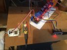
points piggyback board lower left. The white panel carries the lighting PWM outputs and the programming track relays.
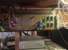
This is where it has to go. The Arduino Nano on the left is the turntable controller, that on the right is the points controller, the ICs are NOT gates to provide the reversing polarity for the Tortoises, the LEDs to the right are green/red and change colour to indicate what the tortoise should have done. Was quite pleased with that, it all works rather well.
The turntable board will require a little reallocation of pins to accommodate the CAN interface. That or another piggy-back might be easier. Might get that done over the weekend.
More soon
Simon

