simond
Western Thunderer
thank you all for your generous "likes". The b****y turntable has suddenly decided not to find its zero point, which is a bit tedious. MrsD complained about the layout "whining" the other day, and I realised that rather than turning to find the datum point, and then setting itself to the coal road, it had been rotating aimlessly for about an hour... I'll have to sort that one out.
Anyway, some folks will be aware that I have recently become the proud owner of an Elegoo Saturn 2, 8K 3D printer (it's like another language, it's all abbreviations and acronyms!) and that I installed it in MissD's bedroom on Friday. No further progress
A number of reasons, but the key amongst them is that I have not developed the model I wish to print to my satisfaction. My "first attempt" was to be the two tool boxes, and the jib support for an L15 match truck, the chassis of which I constructed as part of the breakdown train some two years back. I had built a plasticard rendition of the boxes, but they lack detail as I was putting it off, waiting for this moment.
BUT
The drawings I have (ABT page 221) are inadequate, I have some pictures taken at Didcot of a similar wagon some time back, but i'm chasing my tail trying to make a decent detailed 3D rendition of a thing for which I simply don't have enough data. So when I find an obvious mismatch, I don't know where to go or how to fix it, and that leads to frustration.
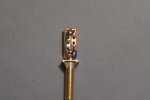
Here's the current plasticard job;
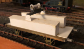
and here's the 3D model
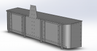
It looks very impressive with all the rivets, but I'm far from convinced they are correctly spaced or placed, or even sized, and I am sure that the pattern on the flange that sticks up is not correct.
I think I am going to have to visit Didcot, and measure and model a known vehicle in order to do a proper job of this. At least I'll not be imagining that the designer ' would have spaced these rivets at 3" centres, and those at 6" ' because it seems that that way, madness lies.
I'm going to slice up what I've modelled, print it to have a go of the printer, and live with it until I can get better data - unless anyone has a better idea?
Hopefully, drawings of suitable axleboxes and springs (and brakes) will be in GWRJ or one of my other references, and I can make a decent fist of generating 3D files for them, that will at least make a start on the underframe details.
I have a massive list of things I want to print, so I'm sure I can keep myself entertained. Some are rather less exacting than others (eg wheelbarrows, sack trucks, a fireplace for the signal box) so maybe they will provide some light entertainment, assuming I can get some basic dimensions.
Thoughts and suggestions very welcome
Simon
Anyway, some folks will be aware that I have recently become the proud owner of an Elegoo Saturn 2, 8K 3D printer (it's like another language, it's all abbreviations and acronyms!) and that I installed it in MissD's bedroom on Friday. No further progress

A number of reasons, but the key amongst them is that I have not developed the model I wish to print to my satisfaction. My "first attempt" was to be the two tool boxes, and the jib support for an L15 match truck, the chassis of which I constructed as part of the breakdown train some two years back. I had built a plasticard rendition of the boxes, but they lack detail as I was putting it off, waiting for this moment.
BUT
The drawings I have (ABT page 221) are inadequate, I have some pictures taken at Didcot of a similar wagon some time back, but i'm chasing my tail trying to make a decent detailed 3D rendition of a thing for which I simply don't have enough data. So when I find an obvious mismatch, I don't know where to go or how to fix it, and that leads to frustration.
Here's the current plasticard job;

and here's the 3D model

It looks very impressive with all the rivets, but I'm far from convinced they are correctly spaced or placed, or even sized, and I am sure that the pattern on the flange that sticks up is not correct.
I think I am going to have to visit Didcot, and measure and model a known vehicle in order to do a proper job of this. At least I'll not be imagining that the designer ' would have spaced these rivets at 3" centres, and those at 6" ' because it seems that that way, madness lies.
I'm going to slice up what I've modelled, print it to have a go of the printer, and live with it until I can get better data - unless anyone has a better idea?
Hopefully, drawings of suitable axleboxes and springs (and brakes) will be in GWRJ or one of my other references, and I can make a decent fist of generating 3D files for them, that will at least make a start on the underframe details.
I have a massive list of things I want to print, so I'm sure I can keep myself entertained. Some are rather less exacting than others (eg wheelbarrows, sack trucks, a fireplace for the signal box) so maybe they will provide some light entertainment, assuming I can get some basic dimensions.
Thoughts and suggestions very welcome
Simon


